Dell PowerEdge R300 Hardware Owner's Manual (PDF) - Page 118
Replacing the Power Distribution Board, System Board (Service-Only Procedure)
 |
View all Dell PowerEdge R300 manuals
Add to My Manuals
Save this manual to your list of manuals |
Page 118 highlights
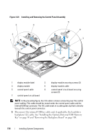
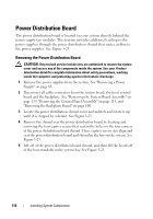
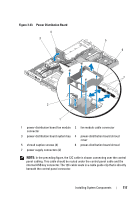
Replacing the Power Distribution Board CAUTION: Only trained service technicians are authorized to remove the system cover and access any of the components inside the system. See your Product Information Guide for complete information about safety precautions, working inside the computer, and protecting against electrostatic discharge. 1 Unpack the new power distribution board assembly. 2 Position and seat the power distribution board over the four standoffs on the chassis base, and then put the power distribution board shroud over the power distribution board and align the standoffs with the four locator holes on the four corners of the power distribution board shroud. See Figure 3-23. 3 Locate, align, and install the four captive screws that seat in the holes on the four corners of the power distribution board shroud. These captive screws also align and seat the power distribution board and shroud in the bay of the chassis base and the system. See Figure 3-23. 4 Connect the fan module cable connector to the power distribution board and then put the power distribution board shroud over the power distribution board, as shown in Figure 3-23. 5 Connect all cables to the system board, front control board, and backplane. See "Installing the System Board Assembly" on page 121, "Installing the Control Panel Assembly" on page 115, and "Installing the Backplane Board" on page 102. 6 Locate the hinged interior catches on either side of the shroud and align and seat the power distribution board cover, rotating it down and over the shroud. See Figure 3-23. 7 Install the power supplies in the system. "Replacing a Power Supply" on page 89. System Board (Service-Only Procedure) The system board and system board tray are removed and replaced as a single assembly. 118 Installing System Components
-
 1
1 -
2
-
3
-
4
-
5
-
6
-
7
-
8
-
9
-
10
-
11
-
12
-
13
-
14
-
15
-
16
-
17
-
18
-
19
-
20
-
21
-
22
-
23
-
24
-
25
-
26
-
27
-
28
-
29
-
30
-
31
-
32
-
33
-
34
-
35
-
36
-
37
-
38
-
39
-
40
-
41
-
42
-
43
-
44
-
45
-
46
-
47
-
48
-
49
-
50
-
51
-
52
-
53
-
54
-
55
-
56
-
57
-
58
-
59
-
60
-
61
-
62
-
63
-
64
-
65
-
66
-
67
-
68
-
69
-
70
-
71
-
72
-
73
-
74
-
75
-
76
-
77
-
78
-
79
-
80
-
81
-
82
-
83
-
84
-
85
-
86
-
87
-
88
-
89
-
90
-
91
-
92
-
93
-
94
-
95
-
96
-
97
-
98
-
99
-
100
-
101
-
102
-
103
-
104
-
105
-
106
-
107
-
108
-
109
-
110
-
111
-
112
-
 113
113 -
 114
114 -
 115
115 -
 116
116 -
 117
117 -
 118
118 -
 119
119 -
 120
120 -
 121
121 -
 122
122 -
 123
123 -
124
-
125
-
126
-
127
-
128
-
129
-
130
-
131
-
132
-
133
-
134
-
135
-
136
-
137
-
138
-
139
-
140
-
141
-
142
-
143
-
144
-
145
-
146
-
147
-
148
-
149
-
150
-
151
-
152
-
153
-
154
-
155
-
156
-
157
-
158
-
159
-
160
-
161
-
162
-
163
-
164
-
165
-
166
-
167
-
168
-
169
-
170
-
171
-
172
-
173
-
174
-
175
-
176
-
177
-
178
-
179
-
180
-
181
-
182
-
183
-
184
 |
 |