Dell PowerVault 110T SDLT320 User Manual - Page 26
Step-by-Step Installation Instructions
 |
View all Dell PowerVault 110T SDLT320 manuals
Add to My Manuals
Save this manual to your list of manuals |
Page 26 highlights
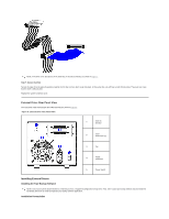
because this will switch the LVD host adapter into single-ended mode and restrict performance. You need the appropriate Ultra 2 or Ultra wide SCSI ribbon cable with the correct termination, provided with the tape drive. (Dell PowerVault drives have 68-pin wide, highdensity SCSI connectors.) If you are using a Dell PowerVault drive on an internal bus with other peripherals that run at Ultra 2 speeds, use a 68-pin LVD-compatible ribbon cable. CAUTION: Static electricity can damage electronic components. Always wear an antistatic wrist strap if possible. If not, to equalize the electromagnetic charges, touch a bare metal part of the system (such as the back plate) before you remove the tape drive from its bag. Mounting Bay You need one industry-standard, 5.25-inch, full-height bay in which to install the PowerVault drive. Ensure that all fans in your system are in place and operational. Make sure that empty bays have the appropriate blanking plates installed so that airflow is maintained. Mounting Hardware Some servers require a special mounting tray or rails to secure the drive into the empty bay. If this is the case with your system, make sure you have the parts before installation. Step-by-Step Installation Instructions Step 1: Setting the SCSI ID Figure 2. Setting the SCSI ID A red dot in the illustration denotes Pin 1 on the jumper block or connector. Your Dell PowerVault drive is shipped with a default SCSI ID of 6, but you can opt to use any unused ID between 0 and 15, except 7. Do not use SCSI ID 7; that ID is reserved for the SCSI controller. NOTE: Each device on the SCSI bus must have a unique SCSI ID address. For specific recommendations for assigning SCSI IDs, refer to the system or SCSI controller documentation. The SCSI ID is set using jumpers on a set of pins at the rear of the drive. Figure 3 shows the empty jumper block that you use to set the SCSI ID. If you decide it is necessary to change the tape drive's SCSI ID, use your fingers to move the jumpers to the pattern corresponding to the ID you want (see Figure 3 and the related table of SCSI jumper settings in Jumpers). Figure 3. Detail of the Empty SCSI ID Jumper Block NOTE: The computer system and the tape drive SCSI IDs are only checked at power-on. To change the SCSI ID after installation, power down both the system and the tape drive, change the drive's SCSI ID, power up the tape drive, and then power up the system.
-
 1
1 -
2
-
3
-
4
-
5
-
6
-
7
-
8
-
9
-
10
-
11
-
12
-
13
-
14
-
15
-
16
-
17
-
18
-
19
-
20
-
 21
21 -
 22
22 -
 23
23 -
 24
24 -
 25
25 -
 26
26 -
 27
27 -
 28
28 -
 29
29 -
 30
30 -
 31
31 -
32
-
33
-
34
-
35
-
36
-
37
-
38
-
39
-
40
-
41
-
42
-
43
 |
 |
