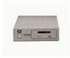
Dell PowerVault 110T SDLT320 User Manual - Page 36
Environmental Specifications
 |
View all Dell PowerVault 110T SDLT320 manuals
Add to My Manuals
Save this manual to your list of manuals |
Page 36 highlights
Additional 30 minutes for each additional resonance; up to 4 resonances total. * Air and truck profiles are specified in ASTM D4728, Standard Test Method for Random Vibration Testing of Shipping Containers. Table 6. Operating Shock and Vibration Specifications Type: Frequency Range: Acceleration level: Application: Pulse Shape: Peak Acceleration: Duration: Application: Sine 5 - 500 - 5 Hz 0.25 G 0.010" DA X,Y,Z axes Shock ½ sine pulse 10 G 10 ms X,Y,Z axes, twice in each axis (once in each direction) Vibration Sweep Upward and downward sweep Between 22 and 500 Hz Between 5 and 22 Hz (crossover) Sweep rate = 1 octave per minute Current and Power Requirements The following table provides the applicable power requirements for both versions of the tape system. The tabletop version requires AC power. The tape drive uses the most current (and power) during its native write modes and backward-read compatibility (BRC) read modes, so they are outlined in the table. Standby is measured with the tape loaded and tensioned or untensioned, and Idle is measured with power on with no tape loaded. (The power drawn in these two modes is similar enough that they are listed together.) Power-up current surges are less than those encountered during motor accelerations, and are not listed separately. NOTE: In Table 7, the current and DC power values are relevant to the internal drive, while the AC power values are relevant to the tabletop drive. Table 7. Current and Power Specifications Mode Standby / Idle Media Loading / Unloading 220/320 Write-Motor Start8 220/320 Write-Streaming Max for SDLT Modes9 5 V Current (A) MaxPk¹ MaxRms² 3.2 3.0 3.8 3.1 6.1 3.1 6.3 4.3 4.3 Typ³ 2.9 2.9 3.0 3.8 12 V Current (A) MaxPk¹ MaxRms² 0.6 0.5 4.8 1.0 4.8 1.0 2.1 0.7 1.0 Typ³ 0.4 0.7 0.7 0.7 DC Power (W) M a x4 Typ5 20 19 25 24 25 24 28 27 28 AC Power (W) M a x6 Typ7 34 29 38 33 33 30 42 38 42 BRC Read-Motor Start8 3.9 3.0 2.8 2.3 0.7 0.6 23 22 38 32 BRC Read-Streaming 5.2 3.3 3.1 1.8 0.7 0.6 24 22 41 33 Max for BRC Modes9 3.3 0.7 24 41 1. The Max-Peak value represents short current spikes drawn for durations of < 50µs. On the 12V supply, the peaks correspond to the pulse width modulated switching of the motors. These values are calculated from the average of Peak-ripple-current + 2 sigma, measured at +5% DC voltage. 2. The Max-Rms value is the average of the maximum RMS current drawn during this operating mode. These values are calculated from the average of RMS current + 3 sigma, measured at nominal DC voltage. 3. The typical current is calculated from the average of all RMS current drawn during this operating mode, measured at nominal DC voltage. 4. The Max DC power is calculated from the typical DC power + 3 sigma, measured at nominal DC voltage. This value takes into account that the peak currents on the 5V and 12V do not occur at the same time. 5. The typical DC power is calculated from the average RMS DC power drawn during this operating mode, measured at nominal DC voltage. This value also takes into account that the peak currents on the 5V and 12V do not occur at the same time. 6. The Max AC power is calculated from the typical AC power in tabletop drives + 3 sigma. 7. The typical AC power is calculated from the average AC power drawn in external drives. 8. The motor start modes draw the most current from the 12V supply, so they are shown separately. These events last < 1 second and occur at a duty cycle of less than 25%. 9. The Max values for each mode are based on the Max-Rms values, since the peak values are of very short duration. Tape System Recording Method The Dell PowerVault tape drive uses the Partial Response Maximum Likelihood (PRML) 32/33 encoding method for reading and writing SDLT 320 and 220 format. Environmental Specifications
-
 1
1 -
2
-
3
-
4
-
5
-
6
-
7
-
8
-
9
-
10
-
11
-
12
-
13
-
14
-
15
-
16
-
17
-
18
-
19
-
20
-
21
-
22
-
23
-
24
-
25
-
26
-
27
-
28
-
29
-
30
-
 31
31 -
 32
32 -
 33
33 -
 34
34 -
 35
35 -
 36
36 -
 37
37 -
 38
38 -
 39
39 -
 40
40 -
 41
41 -
42
-
43
 |
 |
