Dell PowerVault 110T SDLT320 User Manual - Page 28
Step 6: Attach Power and SCSI Cables, Power and SCSI Cable Connectors, Attach
 |
View all Dell PowerVault 110T SDLT320 manuals
Add to My Manuals
Save this manual to your list of manuals |
Page 28 highlights
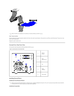
Slide the tape drive into the open bay, aligning the tray or rails with the slots in the bay. A "generic" host system with several unused bays is shown in Figure 5. If your system does not require mounting hardware, check that the holes in the system's chassis are aligned with the holes in the side of the tape drive. Do not fully secure the drive yet; you may have to move it to connect the power and SCSI cables. Step 6: Attach Power and SCSI Cables Figure 6. Power and SCSI Cable Connectors A red dot in the illustration denotes Pin 1 on the jumper block or connector. Attach a spare power cable from the computer system's internal power supply to the power connector, as shown in Figure 6, upper left. Attach a spare SCSI connector on the system's SCSI ribbon cable to the SCSI connector, as shown in Figure 7. (The location of the SCSI connector on the back of the drive is shown in Figure 6, lower right.) Figure 7. Attach the SCSI Connector
-
 1
1 -
2
-
3
-
4
-
5
-
6
-
7
-
8
-
9
-
10
-
11
-
12
-
13
-
14
-
15
-
16
-
17
-
18
-
19
-
20
-
21
-
22
-
 23
23 -
 24
24 -
 25
25 -
 26
26 -
 27
27 -
 28
28 -
 29
29 -
 30
30 -
 31
31 -
 32
32 -
 33
33 -
34
-
35
-
36
-
37
-
38
-
39
-
40
-
41
-
42
-
43
 |
 |
