Dell PowerVault NX3500 Hardware Owner's Manual - Page 11
Indicator, Button, or, Connector, Description, If the system is connected
 |
View all Dell PowerVault NX3500 manuals
Add to My Manuals
Save this manual to your list of manuals |
Page 11 highlights
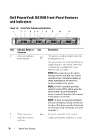
Item Indicator, Button, or Icon Connector 4 LCD panel 5 system identification button 6 System status indicator 7 USB connectors (2) 8 Hard drives (2) 9 System identification panel 10 Optical drive Description Provides system ID, status information, and system error messages. For more information on the LCD panel, see "LCD Panel Features" on page 12. NOTE: If the system is connected to AC power and an error has been detected, the LCD lights amber regardless of whether the system has been powered on. Turns the system ID modes on and off. The identification buttons on the front and back panels can be used to locate a particular system within a rack. When one of these buttons is pushed, the LCD panel on the front and the system status indicator on the chassis back panel light blue until one of the buttons is pushed again. Lights blue during normal system operation. Lights amber when the system needs attention due to a problem. Connect USB devices to the system. The ports are USB 2.0-compliant. Two 3.5-inch hot-swappable SATA drives. A slide-out panel for system information including the Express Service tag, embedded NIC MAC address, and iDRAC6 Enterprise card MAC address. One slim-line SATA DVD-ROM drive or DVD+/-RW drive. NOTE: DVD devices are data only. About Your Solution 11
-
 1
1 -
2
-
3
-
4
-
5
-
 6
6 -
 7
7 -
 8
8 -
 9
9 -
 10
10 -
 11
11 -
 12
12 -
 13
13 -
 14
14 -
 15
15 -
 16
16 -
17
-
18
-
19
-
20
-
21
-
22
-
23
-
24
-
25
-
26
-
27
-
28
-
29
-
30
-
31
-
32
-
33
-
34
-
35
-
36
-
37
-
38
-
39
-
40
-
41
-
42
-
43
-
44
-
45
-
46
-
47
-
48
-
49
-
50
-
51
-
52
-
53
-
54
-
55
-
56
-
57
-
58
-
59
-
60
-
61
-
62
-
63
-
64
-
65
-
66
-
67
-
68
-
69
-
70
-
71
-
72
-
73
-
74
-
75
-
76
-
77
-
78
-
79
-
80
-
81
-
82
-
83
-
84
-
85
-
86
-
87
-
88
-
89
-
90
-
91
-
92
-
93
-
94
-
95
-
96
-
97
-
98
-
99
-
100
-
101
-
102
-
103
-
104
-
105
-
106
-
107
-
108
-
109
-
110
-
111
-
112
-
113
-
114
-
115
-
116
-
117
-
118
 |
 |