Dell Precision 690 User Guide - Page 55
Hard Drive - not booting from dvd
 |
UPC - 683728231804
View all Dell Precision 690 manuals
Add to My Manuals
Save this manual to your list of manuals |
Page 55 highlights
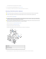
When connecting a SAS or SATA cable, hold the cable by the connector at each end and press firmly into the connector. When disconnecting a SAS or SATA cable, hold the cable by the connector at each end and pull until the connector detaches. SAS Data Cable Connectors 1 SAS/SATA data cable 2 SATA data connector (on the system board) 3 SATA drive SAS Data Cable Connectors 1 power cable 2 SAS/SATA data connector 3 SAS drive 4 SAS interposer connector 5 SAS cable 6 optional PCI Express SAS controller card When connecting an IDE data cable, align the tab on one connector with the notch on the other. When disconnecting an IDE data cable, grasp the colored pull-tab and pull until the connector detaches. When you connect two IDE devices to a single IDE data cable and configure the devices for the cable select setting, the device attached to the last connector on the data cable is primary or the boot device, and the device attached to the middle connector on the data cable is the secondary device. See the drive documentation in your upgrade kit for information on configuring devices for the cable select setting. Hard Drive NOTICE: Do not attempt to install a SAS hard drive in a 5.25-inch drive bay. These drive bays will only support a SATA hard drive, a CD/DVD drive, a floppy drive, or a Media Card Reader. NOTICE: If one SATA drive and any SAS drives are installed, the SATA drive must be the boot drive and should be installed in a 5.25-inch drive bay. NOTICE: It is recommended that you only use SAS cables purchased from Dell. Cables purchased elsewhere are not guaranteed to work with Dell computers. Drive numbering is marked upon the chassis beside the hard-drive bays. Removing a Hard Drive (Hard Drive Bays 1-4) CAUTION: Before you begin any of the procedures in this section, follow the safety instructions located in the Product Information Guide. CAUTION: To guard against electrical shock, always unplug your computer from the electrical outlet before removing the cover.
-
 1
1 -
2
-
3
-
4
-
5
-
6
-
7
-
8
-
9
-
10
-
11
-
12
-
13
-
14
-
15
-
16
-
17
-
18
-
19
-
20
-
21
-
22
-
23
-
24
-
25
-
26
-
27
-
28
-
29
-
30
-
31
-
32
-
33
-
34
-
35
-
36
-
37
-
38
-
39
-
40
-
41
-
42
-
43
-
44
-
45
-
46
-
47
-
48
-
49
-
 50
50 -
 51
51 -
 52
52 -
 53
53 -
 54
54 -
 55
55 -
 56
56 -
 57
57 -
 58
58 -
 59
59 -
 60
60 -
61
-
62
-
63
-
64
-
65
-
66
-
67
-
68
-
69
-
70
-
71
-
72
-
73
-
74
-
75
-
76
-
77
-
78
-
79
-
80
-
81
-
82
-
83
-
84
-
85
-
86
-
87
-
88
-
89
-
90
-
91
-
92
-
93
-
94
-
95
-
96
-
97
-
98
-
99
-
100
-
101
-
102
-
103
-
104
-
105
-
106
-
107
-
108
-
109
-
110
-
111
-
112
-
113
-
114
-
115
-
116
-
117
-
118
-
119
-
120
-
121
-
122
-
123
-
124
-
125
-
126
-
127
-
128
-
129
-
130
-
131
-
132
-
133
-
134
-
135
-
136
-
137
-
138
-
139
-
140
-
141
-
142
-
143
-
144
-
145
-
146
-
147
-
148
-
149
-
150
-
151
-
152
-
153
-
154
-
155
-
156
-
157
-
158
-
159
-
160
-
161
-
162
-
163
-
164
-
165
-
166
-
167
 |
 |
