Dell S3048-ON EMC Networking Virtualization Overlay with BGP EVPN - Page 12
Topology
 |
View all Dell S3048-ON manuals
Add to My Manuals
Save this manual to your list of manuals |
Page 12 highlights
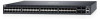
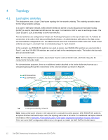
4 Topology 4.1 Leaf-spine underlay This deployment uses a Layer 3 leaf-spine topology for the network underlay. The underlay provides transit for the virtual network overlays. In a Layer 3 leaf-spine network, traffic between leafs and spines is routed. Equal cost multi-path routing (ECMP) is used to load balance traffic across the Layer 3 connections. BGP is used to exchange routes. The Layer 3/Layer 2 (L3/L2) boundary is at the leaf switches. Two leaf switches are configured as Virtual Link Trunking (VLT) peers at the top of each rack. VLT allows all connections to be active while also providing fault tolerance. As administrators add racks to the data center, two leaf switches configured for VLT are added to each new rack. Connections within racks from hosts to leaf switches are Layer 2, and each host is connected using a VLT port channel. In this example, two Z9264F-ON switches are used as spines, two S5248F-ON switches are used as leafs in Rack 1, and four S4148U-ON switches are used as leafs in the remaining two racks. The leafs in the last rack also act as border leafs. Note: For this deployment example, any leaf pair may be used as border leafs, and hosts may also be connected to the border leafs. For demonstration purposes, there is an additional switch attached to the border leafs which serves as a simulated gateway/firewall for connections to the external network as shown in Figure 8. L3 Connection L2 Connection ZS9p2i6n4eF1-1 ZS9p26in4eF-2 ECMP L3 L2 S5248F-1a VLTi S5248F-1b Rack 1 VLT S4148U-2a VLTi S4148U-2b Rack 2 VLT Host Leaf-spine underlay network Host Border Leafs S4148U-3a VLTi L3 S4148U-3b L2 Rack n VLT Gateway/ Firewall Note: Using a leaf-spine network in the data center is considered a best practice. With Z9264F-ON switches as spines and two leaf switches per rack, this topology will scale to 32 racks. For additional leaf-spine network information, refer to Dell EMC PowerSwitch Layer 3 Leaf-Spine Deployment and Best Practices with OS10. There are some BGP configuration differences in this guide to enable the BGP EVPN VXLAN feature. 12 Dell EMC Networking Virtualization Overlay with BGP EVPN
-
 1
1 -
2
-
3
-
4
-
5
-
6
-
 7
7 -
 8
8 -
 9
9 -
 10
10 -
 11
11 -
 12
12 -
 13
13 -
 14
14 -
 15
15 -
 16
16 -
 17
17 -
18
-
19
-
20
-
21
-
22
-
23
-
24
-
25
-
26
-
27
-
28
-
29
-
30
-
31
-
32
-
33
-
34
-
35
-
36
-
37
-
38
-
39
-
40
-
41
-
42
-
43
-
44
-
45
-
46
-
47
-
48
-
49
-
50
-
51
-
52
-
53
-
54
-
55
-
56
-
57
-
58
-
59
-
60
-
61
-
62
-
63
-
64
-
65
-
66
-
67
 |
 |
