Dell S3048-ON EMC Networking Virtualization Overlay with BGP EVPN - Page 15
Underlay network connections
 |
View all Dell S3048-ON manuals
Add to My Manuals
Save this manual to your list of manuals |
Page 15 highlights
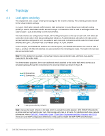
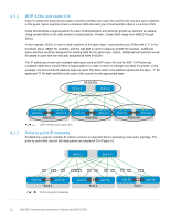
4.2 Underlay network connections The physical underlay network connections are shown in Figure 11. Each leaf has one connection to each spine. 100GbE uplink ports on leafs are used to maximize bandwidth. Each host has one connection to each leaf configured as an LACP port channel on the host and as a VLT port channel on the two leafs. Connections from hosts to S5248F-ON leaf switches are 25GbE. Connections from hosts to S4148U-ON leaf switches are 10GbE (not shown). Z9264F-ON Spine 1 Z9264F-ON Spine 2 Stack ID Reset Stack ID Reset S5248F-ON Stack ID Leaf 1A S5248F-ON Leaf 1B Stack ID VLT port channel VLTi GRN =10G ACT/ LNK A GRN =10G ACT/ LNK B PowerEdge R740xd 25GbE Layer 2 link 100GbE Layer 3 link (Spine 1) 100GbE Layer 3 link (Spine 2) 100GbE VLTi link Production network connections Note: Optionally, the two QSFP28-DD double density ports (2x100GbE interfaces per physical port), available on S5248F-ON switches, may be used for the VLTi instead of the QSFP28 ports (1x100GbE interface per physical port). This requires two QSFP28-DD DAC cables. However, QSFP28-DD ports are not available on S4148U-ONs also used as leaf switches in this guide. For this deployment example, all six leafs use two QSFP28 ports per switch for the VLTi. 15 Dell EMC Networking Virtualization Overlay with BGP EVPN
-
 1
1 -
2
-
3
-
4
-
5
-
6
-
7
-
8
-
9
-
 10
10 -
 11
11 -
 12
12 -
 13
13 -
 14
14 -
 15
15 -
 16
16 -
 17
17 -
 18
18 -
 19
19 -
 20
20 -
21
-
22
-
23
-
24
-
25
-
26
-
27
-
28
-
29
-
30
-
31
-
32
-
33
-
34
-
35
-
36
-
37
-
38
-
39
-
40
-
41
-
42
-
43
-
44
-
45
-
46
-
47
-
48
-
49
-
50
-
51
-
52
-
53
-
54
-
55
-
56
-
57
-
58
-
59
-
60
-
61
-
62
-
63
-
64
-
65
-
66
-
67
 |
 |
