Dell S5148F-ON EMC PowerSwitch Installation Guide July 2021 - Page 28
Power supplies, Components
 |
View all Dell S5148F-ON manuals
Add to My Manuals
Save this manual to your list of manuals |
Page 28 highlights
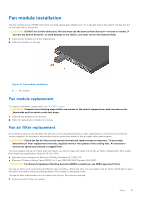
6 Power supplies The S5148F-ON switch ships with two AC or DC power supplies. The two power supplies have two air-flow directions-from the I/O to the PSU and from the PSU to the I/O. Two PSUs are required for full redundancy, but the switch can operate with a single PSU. The PSUs are field replaceable. When running with full redundancy-two power supplies installed and running-you can remove and replace one PSU without disrupting traffic. CAUTION: To prevent electrical shock, ensure that the S5148F-ON switch is grounded properly. If you do not ground your equipment correctly, excessive emissions may result. Use a qualified electrician to ensure that the power cables meet your local electrical requirements. NOTE: Connect the power supply to the appropriate branch circuit protection as defined by your local electrical codes. Verify that the remote power source complies with the switch input power specifications. NOTE: If you use a single PSU, install a blank plate in the other PSU slot. Use power supply 2 (PSU2) as the blank plate slot. To install the blank plate, use a #1 Philips screw driver. NOTE: ESD damage can occur if components are mishandled. Always wear an ESD-preventive wrist or heel ground strap when handling the S5148F-ON switch and components. Topics: • Components • AC or DC power supply installation • DC power supply to power source connection Components The following power supply options are available for the S5148F-ON switch: ● AC or DC power supply with integrated fan ● AC or DC power supply with integrated reverse flow fan Power supply 1 (PSU1) is on the left side of the switch; power supply 2 (PSU2) is on the right side of the switch. Figure 15. S5148F-ON PSUs ● 1-PSU modules The PSUs have an integrated fan, which you cannot replace individually; if the fan integrated in a PSU fails, you must replace the entire PSU. You can replace the fan trays individually. For fan tray replacement procedures, see Fans. WARNING: Prevent exposure and contact with hazardous voltages. Do not attempt to operate this switch with the safety cover removed. 28 Power supplies
-
 1
1 -
2
-
3
-
4
-
5
-
6
-
7
-
8
-
9
-
10
-
11
-
12
-
13
-
14
-
15
-
16
-
17
-
18
-
19
-
20
-
21
-
22
-
 23
23 -
 24
24 -
 25
25 -
 26
26 -
 27
27 -
 28
28 -
 29
29 -
 30
30 -
 31
31 -
 32
32 -
 33
33 -
34
-
35
-
36
-
37
-
38
-
39
-
40
-
41
-
42
-
43
-
44
-
45
 |
 |
