Dell S5148F-ON EMC PowerSwitch Installation Guide July 2021 - Page 35
Management ports, RS-232 console port access
 |
View all Dell S5148F-ON manuals
Add to My Manuals
Save this manual to your list of manuals |
Page 35 highlights
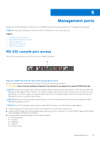
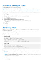
8 Management ports Besides the 10/100/1000Base-T RJ-45 ports, the S5148F-ON switch provides several ports for management and storage. NOTE: The output examples in this section are for reference only. Your output may vary. Topics: • RS-232 console port access • MicroUSB-B console port access • USB storage mount • Before you install an OS • ONIE service discovery RS-232 console port access The RS-232 console port is on the PSU-side of the S5148F-ON switch. Figure 20. S5148F-ON switch RS-232 console and management ports 1. Out-of-band network management port (top); RS-232 serial console port (bottom) CAUTION: Ensure that any equipment attached to the serial port can support the required 115200 baud rate. NOTE: When connecting the RJ45 console to the patch panel or terminal server using Cat5e or Cat6 Ethernet cables, the maximum cable length is 100m. However, if the Ethernet cable is disconnected from the patch panel or terminal server but connected to the RJ45 console, the maximum cable length is 6m. If the cable is longer than 6m when disconnected from the panel or server, your switch may not boot. NOTE: Before starting this procedure, ensure that your PC has a 9-pin serial port and that you have installed a terminal emulation program on the PC. NOTE: If your PC's serial port cannot accept a female DB-9 connector, use a DB-9 male-to-male adaptor. 1. Install the provided RJ-45 connector-side of the provided cable into the switch console port. 2. Install the DB-9 female-side of the provided copper cable into your PC's serial port. Or install the DB-9 cable into other data terminal equipment (DTE) server hardware. 3. Keep the default terminal settings on the console as follows: ● 115200 baud rate ● No parity ● 8 data bits ● 1 stop bit ● No flow control Management ports 35
-
 1
1 -
2
-
3
-
4
-
5
-
6
-
7
-
8
-
9
-
10
-
11
-
12
-
13
-
14
-
15
-
16
-
17
-
18
-
19
-
20
-
21
-
22
-
23
-
24
-
25
-
26
-
27
-
28
-
29
-
 30
30 -
 31
31 -
 32
32 -
 33
33 -
 34
34 -
 35
35 -
 36
36 -
 37
37 -
 38
38 -
 39
39 -
 40
40 -
41
-
42
-
43
-
44
-
45
 |
 |
