Dell Vostro 14 3458 Dell Vostro 143458 Owners Manual - Page 24
Installing the Power Connector, Removing the Display Assembly
 |
View all Dell Vostro 14 3458 manuals
Add to My Manuals
Save this manual to your list of manuals |
Page 24 highlights
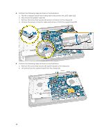
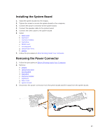
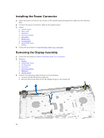
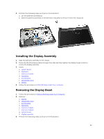
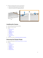
Installing the Power Connector 1. Insert the power connector into its slot on the system board and guide the cable into the retention tabs. 2. Connect the power connector cable to the system board. 3. Install: a. system board b. base cover c. keyboard d. memory module e. hard drive f. WLAN card g. access panel h. optical disk-drive i. battery 4. Follow the procedures in After Working Inside Your computer. Removing the Display Assembly 1. Follow the procedures in Before Working Inside Your Computer. 2. Remove: a. battery b. optical disk-drive c. access panel d. hard drive e. memory module f. keyboard g. system board 3. Perform the following steps as shown in the illustration: a. Unroute the WLAN antenna cables [1]. b. Remove the screws that secure the display hinges to the chassis [2]. 24
-
 1
1 -
2
-
3
-
4
-
5
-
6
-
7
-
8
-
9
-
10
-
11
-
12
-
13
-
14
-
15
-
16
-
17
-
18
-
 19
19 -
 20
20 -
 21
21 -
 22
22 -
 23
23 -
 24
24 -
 25
25 -
 26
26 -
 27
27 -
 28
28 -
 29
29 -
30
-
31
-
32
-
33
-
34
-
35
-
36
-
37
-
38
-
39
-
40
-
41
-
42
-
43
-
44
-
45
-
46
-
47
-
48
 |
 |
