Dell Vostro 14 3458 Dell Vostro 143458 Owners Manual - Page 25
Installing the Display Assembly, Removing the Display Bezel
 |
View all Dell Vostro 14 3458 manuals
Add to My Manuals
Save this manual to your list of manuals |
Page 25 highlights
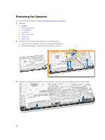
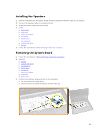
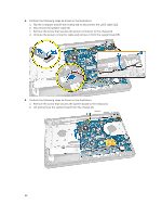
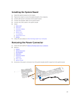
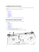
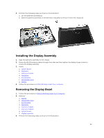
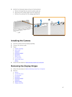
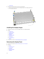
4. Perform the following steps as shown in the illustration: a. Lift the palmrest assembly [1]. b. Slide the palmrest assembly in the direction indicated to remove it from the chassis [2]. Installing the Display Assembly 1. Align the palmrest assembly to the chassis. 2. Route the WLAN antenna cables through their tabs and then tighten the display hinge screws to secure the display assembly. 3. Install: a. system board b. keyboard c. memory module d. hard drive e. access panel f. optical disk-drive g. battery 4. Follow the procedures in After Working Inside Your computer. Removing the Display Bezel 1. Follow the procedures in Before Working Inside Your Computer. 2. Remove: a. battery b. optical disk-drive c. access panel d. hard drive e. memory module f. memory module g. system board h. display assembly 3. Perform the following steps as shown in the illustration: 25
-
 1
1 -
2
-
3
-
4
-
5
-
6
-
7
-
8
-
9
-
10
-
11
-
12
-
13
-
14
-
15
-
16
-
17
-
18
-
19
-
 20
20 -
 21
21 -
 22
22 -
 23
23 -
 24
24 -
 25
25 -
 26
26 -
 27
27 -
 28
28 -
 29
29 -
 30
30 -
31
-
32
-
33
-
34
-
35
-
36
-
37
-
38
-
39
-
40
-
41
-
42
-
43
-
44
-
45
-
46
-
47
-
48
 |
 |
