Dell Vostro 15 3546 Owners Manual
Dell Vostro 15 3546 Manual
 |
View all Dell Vostro 15 3546 manuals
Add to My Manuals
Save this manual to your list of manuals |
Dell Vostro 15 3546 manual content summary:
- Dell Vostro 15 3546 | Owners Manual - Page 1
Dell Vostro 15 - 3546 Owner's Manual Regulatory Model: P45F Regulatory Type: P45F001 - Dell Vostro 15 3546 | Owners Manual - Page 2
potential damage to hardware or loss of data and tells you how to avoid the problem. WARNING: A WARNING indicates a potential for property damage, personal injury, or death. Copyright © 2015 Dell Inc. All rights reserved. This product is protected by U.S. and international copyright and intellectual - Dell Vostro 15 3546 | Owners Manual - Page 3
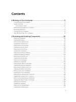
Module...14 Removing the WLAN Card...15 Installing the WLAN Card...15 Removing the Keyboard...15 Installing the Keyboard...16 Removing the Palmrest Assembly...18 Installing the Palmrest Assembly...19 Removing the Battery Connector...20 Installing the Battery Connector...20 Removing the Coin-Cell - Dell Vostro 15 3546 | Owners Manual - Page 4
Existing System and/or Setup Password 41 4 Diagnostics...43 Enhanced Pre-Boot System Assessment (ePSA) Diagnostics 43 Device Status Lights...44 Power Status Lights...44 5 Specifications...45 Specifications...45 6 Contacting Dell 50 Contacting Dell...50 4 - Dell Vostro 15 3546 | Owners Manual - Page 5
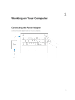
1 Working on Your Computer Connecting the Power Adapter Connect the power adapter and turn on your computer. 5 - Dell Vostro 15 3546 | Owners Manual - Page 6
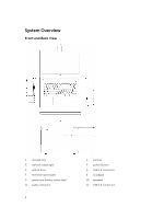
System Overview Front and Back View 1. microphone 3. camera-status light 5. optical drive 7. memory-card reader 9. power and battery-status light 11. audio connector 6 2. camera 4. power button 6. USB 2.0 connector 8. touchpad 10. speakers 12. USB 3.0 connector - Dell Vostro 15 3546 | Owners Manual - Page 7
only perform troubleshooting and simple repairs as authorized in your product documentation, or as directed by the online or telephone service and support team. Damage due to servicing that is not authorized by Dell is not covered by your warranty. Read and follow the safety instructions that came - Dell Vostro 15 3546 | Owners Manual - Page 8
the system board, you must remove the main battery before you service the computer. 7. Remove the main battery. 8. Turn the computer top-side up. 9. before you turn off your computer. 1. Shut down the operating system: • In Windows 8.1: - Using a touch-enabled device: a. Swipe in from the right edge - Dell Vostro 15 3546 | Owners Manual - Page 9
b. Click the Or and select Shut down. * On the Home screen, click • In Windows 7: and then select Shut down. 1. Click Start . 2. Click Shut Down. or computer, use only the battery designed for this particular Dell computer. Do not use batteries designed for other Dell computers. 1. Connect any - Dell Vostro 15 3546 | Owners Manual - Page 10
and Installing Components This section provides detailed information on how to remove or install the components from your computer. Removing the Battery 1. Follow the procedures in Before Working Inside Your Computer. 2. Perform the following steps as shown in the illustration: a. Slide the latches - Dell Vostro 15 3546 | Owners Manual - Page 11
in After Working Inside Your computer. Removing the Optical Drive 1. Follow the procedures in Before Working Inside Your Computer 2. Remove the battery. 3. Perform the following steps as shown in the illustration: a. Remove the screw that secures the optical drive [1]. b. Slide the optical drive - Dell Vostro 15 3546 | Owners Manual - Page 12
in After Working Inside Your computer. Removing the Access Panel 1. Follow the procedures in Before Working Inside Your Computer. 2. Remove the Battery. 3. Perform the following steps as shown in the illustration: a. Loosen the screw that secures access panel to computer [1]. b. Slide the access - Dell Vostro 15 3546 | Owners Manual - Page 13
the Access Panel 1. Insert the access panel into the chassis. 2. Tighten the screw to secure the access panel to the chassis. 3. Install battery. 4. Follow the procedures in After Working Inside Your computer. Removing the Hard Drive 1. Follow the procedures in Before Working Inside Your Computer - Dell Vostro 15 3546 | Owners Manual - Page 14
the procedures in After Working Inside Your computer. Removing the Memory Module 1. Follow the procedures in Before Working Inside Your Computer. 2. Remove: a. battery b. access panel 3. Pry the securing clips away from the memory module until it pops up. 4. Remove the memory module from its socket - Dell Vostro 15 3546 | Owners Manual - Page 15
the screw that secures the WLAN card to the computer. 4. Install the Access panel. 5. Follow the procedures in After Working Inside Your computer. Removing the Keyboard 1. Follow the procedures in Before Working Inside Your Computer. 2. Release the - Dell Vostro 15 3546 | Owners Manual - Page 16
cable to the connector on the system board. 2. Flip the keyboard after connecting the keyboard cable. 3. Slide the keyboard into the retaining slots. 4. Press the top edge to lock the keyboard in place. 5. Install the battery. 6. Follow the procedures in After Working Inside Your computer. If - Dell Vostro 15 3546 | Owners Manual - Page 17
is shipped out for replacement the keyboard cables will not be folded. Follow the instructions below in order to fold the cables correctly: 1. Place the keyboard on a flat and clean surface. 2. Lift the keyboard cable and fold the keyboard-backlight cable at the fold line. 3. Using the alignment - Dell Vostro 15 3546 | Owners Manual - Page 18
Removing the Palmrest Assembly 1. Follow the procedures in Before Working Inside Your Computer. 2. Remove the Battery. 3. Remove the access panel. 4. Remove the keyboard. 5. Flip the computer and remove the screws at the base of the computer. Then, release the tabs securing the base cover. 6. - Dell Vostro 15 3546 | Owners Manual - Page 19
7. Perform the following steps as shown in the illustration: a. Gently pry up the palmrest from the computer [1]. b. Slide the palmrest from the computer [2]. Installing the Palmrest Assembly 1. Place the palmrest on the chassis and press the notches until it clicks in place. 2. Connect the touchpad - Dell Vostro 15 3546 | Owners Manual - Page 20
Connector 1. Follow the procedures in Before Working Inside Your Computer. 2. Remove: a. Battery b. optical disk-drive c. access panel d. hard drive e. memory module f. keyboard g. palmrest assembly 3. Perform the following steps as shown in the illustration: a. Remove the screws that secure the - Dell Vostro 15 3546 | Owners Manual - Page 21
release latch using a scribe and then pull the coin-cell battery to remove it from the computer. Installing the Coin-cell battery 1. Insert the coin-cell battery and press to lock. 2. Install: a. palmrest assembly b. keyboard c. memory module d. hard drive e. WLAN card f. access panel g. optical - Dell Vostro 15 3546 | Owners Manual - Page 22
the Optical Drive Connector 1. Follow the procedures in Before Working Inside Your Computer. 2. Remove: a. battery b. optical disk-drive c. access panel d. hard drive e. memory module f. keyboard g. palmrest assembly 3. Remove the screws that secure the optical drive connector to the computer and - Dell Vostro 15 3546 | Owners Manual - Page 23
the Input/Output (I/0) Board 1. Follow the procedures in Before Working Inside Your Computer. 2. Remove: a. Battery b. optical disk-drive c. access panel d. hard drive e. memory module f. keyboard g. palmrest assembly 3. Perform the following steps as shown in the illustration: a. Lift the locking - Dell Vostro 15 3546 | Owners Manual - Page 24
the chassis. 2. Connect the I/O board cable to the system board. 3. Install: a. palmrest assembly b. keyboard c. memory module d. hard drive e. WLAN card f. access panel g. optical disk-drive h. battery 4. Follow the procedures in After Working Inside Your computer. Removing the Speakers 1. Follow - Dell Vostro 15 3546 | Owners Manual - Page 25
to lock in place. 2. Connect the speakers to the system board. 3. Install: a. palmrest assembly b. keyboard c. memory module d. hard drive e. WLAN card f. access panel g. optical disk-drive h. battery 4. Follow the procedures in After Working Inside Your computer. Removing the System Board 1. Follow - Dell Vostro 15 3546 | Owners Manual - Page 26
h. palmrest assembly. 3. Perform the following steps as shown in the illustration: a. Disconnect speaker and power cable [1]. b. Disconnect display (eDP) cables [2]. 4. Perform the following steps as shown in the illustration a. Lift the locking tab [1]. b. Disconnect I/O cable [2]. c. Disconnect - Dell Vostro 15 3546 | Owners Manual - Page 27
the screws to secure the system board to the computer. 7. Install: a. palmrest assembly b. keyboard c. memory module d. hard drive e. WLAN card f. access panel g. optical disk-drive h. battery 8. Follow the procedures in After Working Inside Your computer. Removing the Display Assembly 1. Follow - Dell Vostro 15 3546 | Owners Manual - Page 28
d. hard drive e. memory module f. keyboard g. palmrest assembly h. system board 3. Unroute the WLAN cable and remove the screws that secure the display panel to the chassis. 4. Place the display panel on a - Dell Vostro 15 3546 | Owners Manual - Page 29
6. Remove the screws securing the display panel to the display assembly. Then, flip the display panel to access the cables underneath. 7. Perform the following steps as shown in the illustration: a. Lift the eDP cable from the computer [1]. b. Disconnect the eDP cable. c. Remove the display panel - Dell Vostro 15 3546 | Owners Manual - Page 30
4. Align and press in the display bezel to the display assembly. 5. Guide the WLAN cables through their tabs and then tighten the display hinge screws to board b. palmrest assembly c. keyboard d. memory module e. hard drive f. access panel g. optical disk-drive h. battery 7. Follow the procedures in - Dell Vostro 15 3546 | Owners Manual - Page 31
Insert the camera into the display assembly. 2. Connect the camera cable. 3. Install: a. display assembly b. palmrest assembly c. keyboard d. memory module e. hard drive f. WLAN card g. access panel h. optical disk-drive i. battery 4. Follow the procedures in After Working Inside Your computer. 31 - Dell Vostro 15 3546 | Owners Manual - Page 32
Removing the Heatsink 1. Follow the procedures in Before Working Inside Your Computer. 2. Remove: a. Battery b. optical disk-drive c. access panel d. hard drive e. memory module f. keyboard g. palmrest assembly h. system board 3. Perform the following steps as shown in the illustration: a. - Dell Vostro 15 3546 | Owners Manual - Page 33
Your Computer. 2. Remove: a. Battery b. optical disk-drive c. access panel d. hard drive e. memory module f. keyboard g. palmrest assembly 3. Perform the the power connector into its slot on the chassis and guide the cable into the retention tabs. 2. Connect the power connector cable to the system - Dell Vostro 15 3546 | Owners Manual - Page 34
3. Install: a. palmrest assembly b. keyboard c. memory module d. hard drive e. WLAN card f. access panel g. optical disk-drive h. battery 4. Follow the procedures in After Working Inside Your computer. 34 - Dell Vostro 15 3546 | Owners Manual - Page 35
Sequence allows you to bypass the System Setup‐defined boot device order and boot directly to a specific device (for example: optical drive or hard drive). During the Power-on Self Test (POST), when the Dell logo appears, you can: • Access System Setup by pressing key • Bring up the one-time - Dell Vostro 15 3546 | Owners Manual - Page 36
of the computer. The table below defines the function of each option. Table 2. Main Options Option System Time System Date BIOS Version Product Name Service Tag Asset Tag CPU Type Description Allows you to reset the time on the computer's internal clock. Allows you to reset the date on the - Dell Vostro 15 3546 | Owners Manual - Page 37
Option CPU Speed CPU ID CPU Cache Fixed HDD L1 Cache L2 Cache L3 Cache SATA ODD AC Adapter Type System Memory Extended Memory Memory Speed Description Displays the speed of the processor. Displays the processor ID. Displays the processor L1 cache size. Displays the processor L2 cache size. - Dell Vostro 15 3546 | Owners Manual - Page 38
Option Integrated NIC USB Emulation USB Wake Support SATA Operation Adapter Warnings Function Key Behavior Battery Health Miscellaneous Devices External USB Ports Microphone Camera Internal Bluetooth Internal WLAN Media Card Reader Optical Drive Boot Disable USB debug Description Enable or disable - Dell Vostro 15 3546 | Owners Manual - Page 39
disable fast boot of system. (Default: Enabled) (Default: UEFI) Enable or disable secure boot. (Default: Enabled) Allows you to load legacy option. (Default: Disabled) Default: Windows Boot Manager Default: Onboard NIC (IPV4) Default: Onboard NIC (IPV6) 39 - Dell Vostro 15 3546 | Owners Manual - Page 40
), on replacing the system board or if an update is available. For laptops, ensure that your computer battery is fully charged and connected to a power outlet 1. Re-start the computer. 2. Go to dell.com/support. 3. Enter the Service Tag or Express Service Code and click Submit. NOTE: To locate the - Dell Vostro 15 3546 | Owners Manual - Page 41
CAUTION: Anyone can access the data stored on your computer if it is not locked and left unattended. NOTE: Your computer is shipped with the system and setup password feature disabled. Assigning a System Password and Setup Password You can assign a new System Password and/or Setup Password or change - Dell Vostro 15 3546 | Owners Manual - Page 42
NOTE: If you change the System and/or Setup password, re-enter the new password when promoted. If you delete the System and/or Setup password, confirm the deletion when promoted. 5. Press and a message prompts you to save the changes. 6. Press to save the changes and exit from the System - Dell Vostro 15 3546 | Owners Manual - Page 43
• View error messages that inform you of problems encountered during testing CAUTION: Use the system window is displayed, listing all devices detected in the computer. The diagnostics starts running the tests on all the detected devices. 4. If you wish to run a diagnostic test on a specific - Dell Vostro 15 3546 | Owners Manual - Page 44
Device Status Lights Icon Description Turns on steadily or blinks to indicate battery charge status. Power Status Lights If the computer is connected to an electrical outlet, the battery light operates as follows: Solid yellow light Light off (AC adapter connected) Light off (AC adapter - Dell Vostro 15 3546 | Owners Manual - Page 45
Specifications Specifications NOTE: Offerings may vary by region. For more information regarding the configuration of your computer, click Start (Start icon) → Help and Support • 4th Generation Intel Core i3 Processor (U-Processor Line) • 4th Generation Intel Core i5 Processor (U-Processor Line) • - Dell Vostro 15 3546 | Owners Manual - Page 46
bus: External display support Table 11. Camera ) Intel HDA bus 2 x 2 W program menu and keyboard media-control keys Description eDP Intel HD Graphics (shared memory) (maximum) 74° Description 10/100/1000 Mbps Ethernet LAN on Motherboard (LOM) • Wi-Fi 802.11 b/g/n • Bluetooth 4.0 Description one headphone - Dell Vostro 15 3546 | Owners Manual - Page 47
ports NOTE: The powered USB 3.0 connector also supports Microsoft Kernel Debugging. The ports are identified in closed) to 135° 60 Hz 40° / 40° 10° / 30° 0.252 mm x 0.252 mm Table 15. Keyboard Feature Number of keys: Description US 101, Brazil 104, UK 102, and Japan 105 Table 16. Touchpad Feature - Dell Vostro 15 3546 | Owners Manual - Page 48
Feature Type Dimensions: Height Width Depth Weight Life span Voltage Temperature range: Operating Non-Operating Coin-cell battery Table 18. AC Adapter Feature Type Input voltage Input current (maximum) Input frequency Output power Output current Rated output voltage Temperature range: Operating - Dell Vostro 15 3546 | Owners Manual - Page 49
contaminant level Description 0 °C to 40 °C (32 °F to 104 °F) -40 °C to 65 °C (-40 °F to 149 °F) 10 % to 90 % (non-condensing) 0 % to 95 % (non-condensing) -15.2 m to 3048 m (-50 to 10,000 ft) 0° to 35°C -15.2 m to 10,668 m (-50 ft to 35,000 ft) G1 as defined by ISA-S71.04-1985 49 - Dell Vostro 15 3546 | Owners Manual - Page 50
options. Availability varies by country and product, and some services may not be available in your area. To contact Dell for sales, technical support, or customer service issues: 1. Go to dell.com/support. 2. Select your support category. 3. Verify your country or region in the Choose a Country
-
 1
1 -
 2
2 -
 3
3 -
 4
4 -
 5
5 -
 6
6 -
 7
7 -
8
-
9
-
10
-
11
-
12
-
13
-
14
-
15
-
16
-
17
-
18
-
19
-
20
-
21
-
22
-
23
-
24
-
25
-
26
-
27
-
28
-
29
-
30
-
31
-
32
-
33
-
34
-
35
-
36
-
37
-
38
-
39
-
40
-
41
-
42
-
43
-
44
-
45
-
46
-
47
-
48
-
49
-
50
 |
 |

Dell Vostro 15 – 3546
Owner's Manual
Regulatory Model: P45F
Regulatory Type: P45F001