Dell Vostro 15 3546 Owners Manual - Page 31
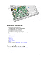
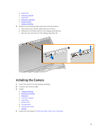
Installing the Camera
 |
View all Dell Vostro 15 3546 manuals
Add to My Manuals
Save this manual to your list of manuals |
Page 31 highlights
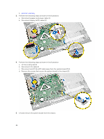
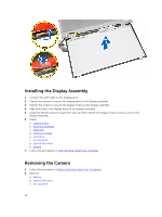
d. hard drive e. memory module f. keyboard g. palmrest assembly h. system board i. display assembly 3. Perform the following steps as shown in the illustration: a. Disconnect the camera cable from the camera. b. Release the retention tab from the display assembly [1]. c. Remove the camera from the display assembly [2]. Installing the Camera 1. Insert the camera into the display assembly. 2. Connect the camera cable. 3. Install: a. display assembly b. palmrest assembly c. keyboard d. memory module e. hard drive f. WLAN card g. access panel h. optical disk-drive i. battery 4. Follow the procedures in After Working Inside Your computer. 31
-
 1
1 -
2
-
3
-
4
-
5
-
6
-
7
-
8
-
9
-
10
-
11
-
12
-
13
-
14
-
15
-
16
-
17
-
18
-
19
-
20
-
21
-
22
-
23
-
24
-
25
-
 26
26 -
 27
27 -
 28
28 -
 29
29 -
 30
30 -
 31
31 -
 32
32 -
 33
33 -
 34
34 -
 35
35 -
 36
36 -
37
-
38
-
39
-
40
-
41
-
42
-
43
-
44
-
45
-
46
-
47
-
48
-
49
-
50
 |
 |
d.
hard drive
e.
memory module
f.
keyboard
g.
palmrest assembly
h.
system board
i.
display assembly
3.
Perform the following steps as shown in the illustration:
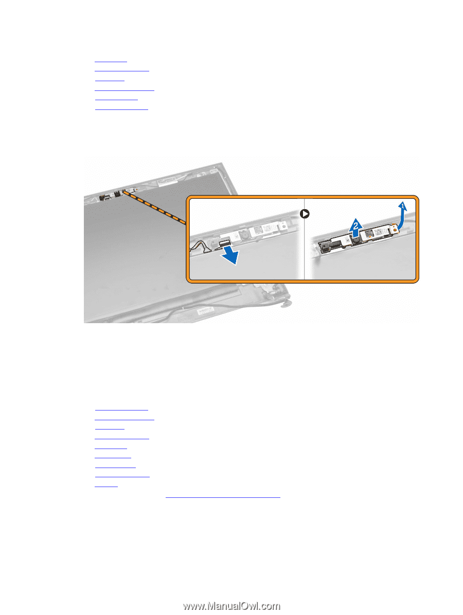
a.
Disconnect the camera cable from the camera.
b.
Release the retention tab from the display assembly [1].
c.
Remove the camera from the display assembly [2].
Installing the Camera
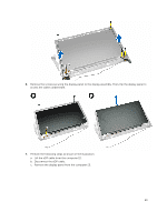
1.
Insert the camera into the display assembly.
2.
Connect the camera cable.
3.
Install:
a.
display assembly
b.
palmrest assembly
c.
keyboard
d.
memory module
e.
hard drive
f.
WLAN card
g.
access panel
h.
optical disk-drive
i.
battery
4.
Follow the procedures in
After Working Inside Your computer
.
31