Dell Vostro 5515 Vostro 15 5515 Service Manual
Dell Vostro 5515 Manual
 |
View all Dell Vostro 5515 manuals
Add to My Manuals
Save this manual to your list of manuals |
Dell Vostro 5515 manual content summary:
- Dell Vostro 5515 | Vostro 15 5515 Service Manual - Page 1
Vostro 15 5515 Service Manual Regulatory Model: P106F Regulatory Type: P106F003 April 2021 Rev. A01 - Dell Vostro 5515 | Vostro 15 5515 Service Manual - Page 2
use of your product. CAUTION: A CAUTION indicates either potential damage to hardware or loss of data and tells you how to avoid the problem. WARNING: A WARNING indicates a potential for property damage, personal injury, or death. © 2021 Dell Inc. or its subsidiaries. All rights reserved. Dell, EMC - Dell Vostro 5515 | Vostro 15 5515 Service Manual - Page 3
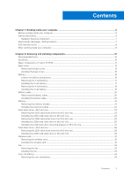
Chapter 1: Working inside your computer 6 Before working inside your computer...6 Safety instructions...6 Radiation Exposure Statement ...7 Electrostatic discharge-ESD protection...7 ESD field service kit ...8 After working inside your computer...8 Chapter 2: Removing and installing components - Dell Vostro 5515 | Vostro 15 5515 Service Manual - Page 4
password...69 Deleting or changing an existing system setup password 69 Clearing BIOS (System Setup) and System passwords 70 Chapter 5: Troubleshooting...71 Dell SupportAssist Pre-boot System Performance Check diagnostics 71 Running the SupportAssist Pre-Boot System Performance Check 71 System - Dell Vostro 5515 | Vostro 15 5515 Service Manual - Page 5
Recovering the operating system...73 Flashing BIOS (USB key)...73 Flashing the BIOS...73 M-BIST...74 LCD Built-in Self Test (BIST)...74 WiFi power cycle...74 Flea power release...75 Chapter 6: Getting help and contacting Dell 76 Contacting Dell...77 Contents 5 - Dell Vostro 5515 | Vostro 15 5515 Service Manual - Page 6
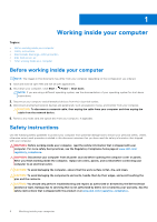
and the contacts. CAUTION: You should only perform troubleshooting and repairs as authorized or directed by the Dell technical assistance team. Damage due to servicing that is not authorized by Dell is not covered by your warranty. See the safety instructions that is shipped with the product or at - Dell Vostro 5515 | Vostro 15 5515 Service Manual - Page 7
circuits in ways that may not be obvious, such as intermittent problems or a shortened product life span. As the industry pushes for memory errors, etc. The more difficult type of damage to recognize and troubleshoot is the intermittent (also called latent or "walking wounded") failure. Perform - Dell Vostro 5515 | Vostro 15 5515 Service Manual - Page 8
physical connection of the wrist strap and bonding wire between your skin, the ESD mat, and the hardware is known as bonding. Use only Field Service kits with a wrist strap, mat, and bonding wire. Never use wireless wrist straps. Always be aware that the internal wires of a wrist strap are prone - Dell Vostro 5515 | Vostro 15 5515 Service Manual - Page 9
5. Turn on your computer. Working inside your computer 9 - Dell Vostro 5515 | Vostro 15 5515 Service Manual - Page 10
2 Removing and installing components NOTE: The images in this document may differ from your computer depending on the configuration you ordered. Topics: • Recommended tools • Screw list • Major components of Vostro 15 5515 • Base cover • Battery • Battery cable • Memory • Solid-state drive-M.2 slot - Dell Vostro 5515 | Vostro 15 5515 Service Manual - Page 11
Table 1. Screw list Component Base cover Screw type ● Captive screws M2x7.5 ● M2x4 Quantity ●2 ●7 3-cell battery 4-cell battery Wireless card Solid-state drive - Slot 1 Solid-state drive - Slot 2 Fan Heat sink System board M2x3 3 M2x3 4 M2x3 1 M2x3 1 M2x3 1 M2x3 2 Captive screws 4 - Dell Vostro 5515 | Vostro 15 5515 Service Manual - Page 12
1. Base cover 2. Heat sink 3. System board 4. Memory 5. Battery 6. Right speaker 7. Palm-rest and keyboard assembly 8. Touchpad 9. Display assembly 10. Coin-cell battery 11. I/O board 12. M.2 2280 solid-state drive, if installed 13. Wireless card 14. M.2 2230 solid-state drive, if installed 15. - Dell Vostro 5515 | Vostro 15 5515 Service Manual - Page 13
16. Fan 17. Power-adapter port NOTE: Dell provides a list of components and their part numbers for the original system configuration purchased. These parts are available according to warranty coverages purchased by the customer. Contact your Dell sales representative for purchase options. Base cover - Dell Vostro 5515 | Vostro 15 5515 Service Manual - Page 14
1. Loosen the two (M2x7.5) captive screws that secure the base cover to the palm-rest and keyboard assembly. 2. Remove the seven (M2x4) screws that secure the base cover to the palm-rest and keyboard assembly. 3. Using a plastic scribe, pry the base cover from the U-shaped indents at the top edge of - Dell Vostro 5515 | Vostro 15 5515 Service Manual - Page 15
7. Press and hold the power button for 20 seconds to ground the computer and drain the flea power. Installing the base cover If you are replacing a component, remove the existing component before performing the installation procedure. The following images indicate the location of the base cover and - Dell Vostro 5515 | Vostro 15 5515 Service Manual - Page 16
any kind to pry on or against the battery. ● Ensure any screws during the servicing of this product are not lost or misplaced, to prevent accidental puncture or damage to the , contact Dell technical support for assistance. See www.dell.com/contactdell. 16 Removing and installing components - Dell Vostro 5515 | Vostro 15 5515 Service Manual - Page 17
● Always purchase genuine batteries from www.dell.com or authorized Dell partners and resellers. Removing the 3-cell battery 1. Follow the procedure in Before working inside your computer. 2. Remove the base cover. The following image indicates the location of the 3-cell (41 Wh) battery and provides - Dell Vostro 5515 | Vostro 15 5515 Service Manual - Page 18
1. Using the alignment posts, place the 3-cell battery on the palm-rest and keyboard assembly. 2. Align the screw holes on the 3-cell battery with the screw holes on the palm-rest and keyboard assembly. 3. Replace the three (M2x3) screws that secure the 3-cell battery to the palm-rest and keyboard - Dell Vostro 5515 | Vostro 15 5515 Service Manual - Page 19
1. Peel the tape that secures the battery cable to the system board. 2. Disconnect the battery cable from the system board. 3. Remove the four (M2x3) screws that secure the 4-cell battery to the palm-rest and keyboard assembly. 4. Lift the 4-cell battery, along with its cable, off the palm-rest and - Dell Vostro 5515 | Vostro 15 5515 Service Manual - Page 20
, whichever applicable. NOTE: If battery is disconnected from system board for service, then there is a delay during system boot as the system undergoes . 1. Flip the battery and remove the battery cable from the routing guides on the battery. 2. Disconnect the battery cable from the connector on - Dell Vostro 5515 | Vostro 15 5515 Service Manual - Page 21
1. Align and place the battery cable on the battery. 2. Route the battery cable through the routing guides on the battery. 3. Connect the battery cable to the connector on the battery. 1. Install the 3-cell battery or 4-cell battery, whichever applicable. 2. Install the base - Dell Vostro 5515 | Vostro 15 5515 Service Manual - Page 22
1. Lift the Mylar to access the memory module. 2. Use your fingertips to pull the securing clips from both sides of the memory module until the memory module pops-up. 3. Remove the memory module from the memory-module slot. NOTE: Repeat step 1 to step 3 to remove any other memory modules installed - Dell Vostro 5515 | Vostro 15 5515 Service Manual - Page 23
1. Lift the Mylar to access the memory-module slot. 2. Align the notch on the memory module with the tab on the memory-module slot. 3. Slide the memory module firmly at an angle, into the memory-module slot. 4. Press the memory module down until it clicks into place. NOTE: If you do not hear the - Dell Vostro 5515 | Vostro 15 5515 Service Manual - Page 24
NOTE: Solid-state drives are fragile. Exercise care when handling the solid-state drive. NOTE: Depending on the configuration ordered, your computer may support a 2230 solid-state drive, or a 2280 solid-state drive in M.2 slot one. NOTE: This procedure applies only if you are installing a 2230 solid - Dell Vostro 5515 | Vostro 15 5515 Service Manual - Page 25
-state drive while the computer is in sleep or on state. 2. Remove the base cover. NOTE: Depending on the configuration ordered, your computer may support a 2280 solid-state drive, or a 2230 solid-state drive in M.2 slot one. NOTE: This procedure applies only to computers shipped with a 2280 solid - Dell Vostro 5515 | Vostro 15 5515 Service Manual - Page 26
: Solid-state drives are fragile. Exercise care when handling the solid-state drive. NOTE: Depending on the configuration ordered, the computer one may support a 2280 solid-state drive, or a 2230 solid-state drive in M.2 slot one. NOTE: This procedure is applicable if you are installing a 2280 solid - Dell Vostro 5515 | Vostro 15 5515 Service Manual - Page 27
1. Align the notch on the 2280 solid-state drive with the tab on the solid-state drive slot. 2. Slide the 2280 solid-state drive firmly into the solid-state drive slot at an angle. 3. Align the screw hole on the solid-state drive with the screw hole on the palm-rest and keyboard assembly. 4. Replace - Dell Vostro 5515 | Vostro 15 5515 Service Manual - Page 28
2280 solid-state drive, whichever applicable. Solid-state drive-M.2 slot two Removing the 2230 solid-state drive from M.2 slot two NOTE: M.2 slot two supports only 2230 solid-state drive. NOTE: This procedure applies only to computers shipped with a 2230 solid-state drive installed in M.2 slot two - Dell Vostro 5515 | Vostro 15 5515 Service Manual - Page 29
performing the installation procedure. NOTE: Solid-state drives are fragile. Exercise care when handling the solid-state drive. NOTE: M.2 slot two supports only 2230 solid-state drive. NOTE: This procedure applies only to computers shipped with a 2230 solid-state drive installed in M.2 slot two - Dell Vostro 5515 | Vostro 15 5515 Service Manual - Page 30
The following image indicates the location of the 2230 solid-state drive that is installed in M.2 slot two and provides a visual representation of the installation procedure. 1. Align the notch on the 2230 solid-state drive with the tab on M.2 slot two on the system board. 2. Slide the 2230 solid- - Dell Vostro 5515 | Vostro 15 5515 Service Manual - Page 31
Wireless card Removing the wireless card 1. Follow the procedure in Before working inside your computer. 2. Remove the base cover. The following images indicate the location of the wireless card and provide a visual representation of the removal procedure. 1. Remove the screw (M2x3) that secures - Dell Vostro 5515 | Vostro 15 5515 Service Manual - Page 32
the antenna cables to the wireless card. The following table provides the antenna-cable color scheme for the wireless card that is supported by your computer. Table 2. Antenna-cable color scheme Connectors on the wireless card Antenna-cable color Main White Auxiliary Black Silkscreen marking - Dell Vostro 5515 | Vostro 15 5515 Service Manual - Page 33
Fan Removing the fan 1. Follow the procedure in Before working inside your computer. 2. Remove the base cover. The following images indicate the location of the fan and provide a visual representation of the removal procedure. 1. Disconnect the fan cable from the system board. 2. Remove the two ( - Dell Vostro 5515 | Vostro 15 5515 Service Manual - Page 34
1. Using the alignment posts, place the fan on the palm-rest and keyboard assembly. 2. Replace the two (M2x3) screws to secure the fan to the palm-rest and keyboard assembly. 3. Connect the fan cable to the system board. 1. Install the base cover. 2. Follow the procedure in After working inside your - Dell Vostro 5515 | Vostro 15 5515 Service Manual - Page 35
1. Disconnect the coin-cell battery cable from the I/O board. 2. Using the flat-end of a plastic scribe, peel the coin-cell battery from the palm-rest and keyboard assembly. Installing the coin-cell battery If you are replacing a component, remove the existing component before performing the - Dell Vostro 5515 | Vostro 15 5515 Service Manual - Page 36
1. Adhere the coin-cell battery to the slot on the palm-rest and keyboard assembly. 2. Connect the coin-cell battery cable to the I/O board. 1. Install the base cover. 2. Follow the procedure in After working inside your computer. Heat sink Removing the heatsink 1. Follow the procedure in Before - Dell Vostro 5515 | Vostro 15 5515 Service Manual - Page 37
1. In reverse sequential order (as indicated on the heat sink), loosen the four captive screws that secure the heat sink to the system board. 2. Lift the heat sink off the system board. Installing the heatsink If you are replacing a component, remove the existing component before performing the - Dell Vostro 5515 | Vostro 15 5515 Service Manual - Page 38
1. Align the screw holes on the heat sink with the screw holes on the system board. 2. In sequential order (as indicated on the heat sink), tighten the four captive screws that secure the heat sink to the system board. 1. Install the base cover. 2. Follow the procedure in After working inside your - Dell Vostro 5515 | Vostro 15 5515 Service Manual - Page 39
1. Remove the two (M2x5) screws that secure the network-port bracket to the I/O board. 2. Lift the network-port bracket off the I/O board. Installing the network-port bracket If you are replacing a component, remove the existing component before performing the installation process. The following - Dell Vostro 5515 | Vostro 15 5515 Service Manual - Page 40
3. Replace the two (M2x5) screws that secure the network-port bracket to the I/O board. 1. Install the base cover. 2. Follow the procedure in After working inside your computer. I/O board Removing the I/O board 1. Follow the procedure in Before working inside your computer. 2. Remove the base cover. - Dell Vostro 5515 | Vostro 15 5515 Service Manual - Page 41
1. Slide the I/O board into the slots on the palm-rest and keyboard assembly. 2. Align the screw hole on the I/O board with the screw hole on the palm-rest and keyboard assembly. 3. Replace the screw (M2x2) that secures the I/O board to the palm-rest and keyboard assembly. 4. Connect the power- - Dell Vostro 5515 | Vostro 15 5515 Service Manual - Page 42
cable, keyboard cable, and the touchpad cable from the system board. 2. Note the speaker cable routing, and remove the speaker cable from the routing guides on the palm-rest and keyboard assembly. 3. Peel the tape that secures the speaker cable to the palm-rest and keyboard assembly. 4. Disconnect - Dell Vostro 5515 | Vostro 15 5515 Service Manual - Page 43
slots of the palm-rest and keyboard assembly. 2. Connect the speaker cable to the system board. 3. Route the speaker cable through the routing guides on the palm-rest and keyboard assembly. 4. Connect the keyboard backlit cable, keyboard cable, and the touchpad cable to its connectors on the system - Dell Vostro 5515 | Vostro 15 5515 Service Manual - Page 44
The following images indicate the location of the touchpad and provide a visual representation of the removal procedure. 1. Open the latch and disconnect the touchpad cable from the system board. 2. Remove the three (M1.6x2) screws that secure the touchpad bracket to the palm-rest and keyboard - Dell Vostro 5515 | Vostro 15 5515 Service Manual - Page 45
1. Slide the touchpad into the slot on the palm-rest and keyboard assembly. NOTE: Turn the computer over and open the display. Ensure that the touchpad is equally aligned along all four sides. 2. Replace the two (M2x1.8) screws that secure the touchpad to the palm-rest and keyboard assembly. 3. - Dell Vostro 5515 | Vostro 15 5515 Service Manual - Page 46
46 Removing and installing components - Dell Vostro 5515 | Vostro 15 5515 Service Manual - Page 47
1. Peel the tape that secures the display cable to the system board. 2. Open the latch and disconnect the display cable from the system board. 3. Remove the three (M2.5x4.5) screws that secure the left-display hinge to the system board. 4. Remove the three (M2.5x4.5) screws that secure the right- - Dell Vostro 5515 | Vostro 15 5515 Service Manual - Page 48
1. Slide the display assembly at an angle, and place the display assembly on the palm-rest and keyboard assembly. 2. Using the alignment posts, close the display hinges. 3. Replace the three (M2.5x4.5) screws that secure the right-display hinge to the system board. 4. Replace the three (M2.5x4.5) - Dell Vostro 5515 | Vostro 15 5515 Service Manual - Page 49
Power button with optional fingerprint reader Removing the power button with optional fingerprint reader 1. Follow the procedure in Before working inside your computer. 2. Remove the base cover. 3. Remove the I/O board. The following images indicate the location of the power-button with optional - Dell Vostro 5515 | Vostro 15 5515 Service Manual - Page 50
1. Align and place the power button with optional fingerprint reader on the palm-rest and keyboard assembly. 2. Replace the screw (M2x3) that secures the power button with optional fingerprint reader to the palm-rest and keyboard assembly. 1. Install the I/O board. 2. Install the base cover. 3. - Dell Vostro 5515 | Vostro 15 5515 Service Manual - Page 51
board. 4. Peel the tape that secures the power-adapter port cable to the system board. 5. Remove the power-adapter port cable from the routing guide on the palm-rest and keyboard assembly. 6. Lift the power-adapter port, along with its cable, off the palm-rest and keyboard assembly. Installing - Dell Vostro 5515 | Vostro 15 5515 Service Manual - Page 52
and keyboard assembly. 2. Route the power-adapter port cable through the routing guide on the palm-rest and keyboard assembly. 3. Adhere the tape that secures the your computer. NOTE: Your computer's Service Tag is stored in the system board. You must enter the Service Tag in the BIOS setup program - Dell Vostro 5515 | Vostro 15 5515 Service Manual - Page 53
NOTE: When removing the system board to replace/access other parts, the system board can be removed and installed with the heat sink attached in order to simplify the procedure and preserve the thermal bond between the system board and heat-sink. The following image indicates the connectors on your - Dell Vostro 5515 | Vostro 15 5515 Service Manual - Page 54
54 Removing and installing components - Dell Vostro 5515 | Vostro 15 5515 Service Manual - Page 55
to simplify the procedure and preserve the thermal bond between the system board and heat-sink. NOTE: Your computer's Service Tag is stored in the system board. You must enter the Service Tag in the BIOS setup program after you replace the system board. NOTE: Replacing the system board removes any - Dell Vostro 5515 | Vostro 15 5515 Service Manual - Page 56
Figure 2. System board connectors 1. Display cable connector 2. Power-adapter port cable connector 3. Keyboard backlit cable connector 4. Keyboard cable connector 5. Touchpad cable connector 6. Battery cable connector 7. Fan cable connector 8. Speaker cable connector 9. I/O-board cable connector The - Dell Vostro 5515 | Vostro 15 5515 Service Manual - Page 57
Removing and installing components 57 - Dell Vostro 5515 | Vostro 15 5515 Service Manual - Page 58
1. Align and place the system board on the palm-rest and keyboard assembly. 2. Replace the three (M2x2) screws that secure the system board to the palm-rest and keyboard assembly. 3. Connect the display cable to the system board and close the latch to secure the cable. 4. Adhere the tape that - Dell Vostro 5515 | Vostro 15 5515 Service Manual - Page 59
15. Close the right display hinge. 16. Replace the three (M2.5x4.5) screws that secure the right display-hinge to the palm-rest and keyboard assembly. 1. Install the heat sink. 2. Install the fan. 3. Install the wireless card. 4. Install the M.2 2280 solid-state drive or M.2 2230 solid-state drive - Dell Vostro 5515 | Vostro 15 5515 Service Manual - Page 60
Installing the palm-rest and keyboard assembly If you are replacing a component, remove the existing component before performing the installation procedure. Place the palm-rest and keyboard assembly on a flat surface. 60 Removing and installing components - Dell Vostro 5515 | Vostro 15 5515 Service Manual - Page 61
1. Install the display assembly. 2. Install the touchpad. 3. Install the speakers. 4. Install the power-adapter port. 5. Install the power-button with optional fingerprint reader. 6. Install the system board. NOTE: The system board can be installed along with the heat sink. 7. Install the I/O board. - Dell Vostro 5515 | Vostro 15 5515 Service Manual - Page 62
3 Drivers and downloads When troubleshooting, downloading or installing drivers it is recommended that you read the Dell Knowledge Based article, Drivers and Downloads FAQ SLN128938. 62 Drivers and downloads - Dell Vostro 5515 | Vostro 15 5515 Service Manual - Page 63
4 System setup CAUTION: Unless you are an expert computer user, do not change the settings in the BIOS Setup program. Certain changes can make your computer work incorrectly. NOTE: Before you change BIOS Setup program, it is recommended that you write down the BIOS Setup program screen information - Dell Vostro 5515 | Vostro 15 5515 Service Manual - Page 64
ownership date of the computer in MM/DD/YYYY format. BIOS Version Product Name Service Tag Asset Tag CPU Type CPU Speed CPU ID CPU Cache L1 Cache L2 computer. Displays the system model name of the computer. Displays the service tag of the computer. Displays the asset tag of the computer. Displays - Dell Vostro 5515 | Vostro 15 5515 Service Manual - Page 65
Table 4. System setup options-Advance menu Advance Integrated NIC USB Emulation SATA Operation Adapter Warnings Function Key Behavior Keyboard Illumination Keyboard Backlight with AC ● Enabled (Default) ● Disabled Allows pre-OS and early OS networking features to use any enabled NICs. Options are: - Dell Vostro 5515 | Vostro 15 5515 Service Manual - Page 66
Table 4. System setup options-Advance menu (continued) Advance Internal Bluetooth Allows to Switch-on/switch-off the Bluetooth. Options are: ● Enabled (Default) ● Disabled Internal WLAN Allows to Switch-on/switch-off the Wireless Card. Options are: ● Enabled (Default) ● Disabled Media Card - Dell Vostro 5515 | Vostro 15 5515 Service Manual - Page 67
Threshold Performs SupportAssist OS recovery after the set value failed boot attempts. Options are: ● Off ●1 ● 2 (Default) ●3 Support Assist OS Recovery Enabled Support Assist OS recovery on failed boot attempts. Options are: ● Disabled ● Enabled (Default) Table 5. System setup options-Security - Dell Vostro 5515 | Vostro 15 5515 Service Manual - Page 68
Table 5. System setup options-Security menu Security Attestation Enable Key Storage Enable SHA-256 Clear PPI Bypass for Clear Commands TPM Status UEFI Firmware Capsule Updates ● Disabled (Default) ● Enabled Provides for the user to control whether the TPM Endorsement Hierarchy is available to the - Dell Vostro 5515 | Vostro 15 5515 Service Manual - Page 69
Table 7. System setup options-Exit menu Exit Exit Saving Changes Exit the System Setup saving the changes made to the Setup Options. Save Change Without Exit Save the Changes made to the System Setup and continue the Setup. Exit Discarding Changes Exit the System Setup without saving the - Dell Vostro 5515 | Vostro 15 5515 Service Manual - Page 70
. Clearing BIOS (System Setup) and System passwords NOTE: To conduct a BIOS and System password reset, you must call the Dell Tech Support number in your region. 1. Key in your computer's service tag number into the locked BIOS/system setup screen. 2. Convey the code generated to the Dell Tech - Dell Vostro 5515 | Vostro 15 5515 Service Manual - Page 71
inform you if tests are completed successfully ● View error messages that inform you of problems encountered during testing NOTE: Some tests for specific devices require user interaction. Always ensure that displayed. Note the error code and validation number and contact Dell. Troubleshooting 71 - Dell Vostro 5515 | Vostro 15 5515 Service Manual - Page 72
board. BIOS recovery image not found Flash latest BIOS version. If problem persists, replace the system board. BIOS recovery image found but invalid Flash latest BIOS version. If problem persists, replace the system board. Power rail failure Replace the system board. 72 Troubleshooting - Dell Vostro 5515 | Vostro 15 5515 Service Manual - Page 73
: 1. Turn on your computer. 2. Go to www.dell.com/support. 3. Click Product support, enter the Service Tag of your computer, and then click Submit. NOTE: If you do not have the Service Tag, use the auto-detect feature or manually browse for your computer model. 4. Click Drivers & downloads > Find - Dell Vostro 5515 | Vostro 15 5515 Service Manual - Page 74
instructions on the screen. M-BIST M-BIST (Built In Self-Test) diagnostics tool, featuring improved accuracy in system board failures. NOTE: M-BIST can be manually b. AMBER: Indicates a problem with the system board instructions on how to conduct a WiFi power cycle: NOTE: Some ISPs (Internet Service - Dell Vostro 5515 | Vostro 15 5515 Service Manual - Page 75
that remains on the computer even after it has been powered off and the battery has been removed. The following procedure provides the instructions on how to conduct flea power release: 1. Turn off your computer. 2. Disconnect the power adapter from your computer. 3. Press and hold the power - Dell Vostro 5515 | Vostro 15 5515 Service Manual - Page 76
about your computer through videos, manuals and documents. Your Dell computer is uniquely identified by a Service Tag or Express Service Code. To view relevant support resources for your Dell computer, enter the Service Tag or Express Service Code at www.dell.com/support. For more information on - Dell Vostro 5515 | Vostro 15 5515 Service Manual - Page 77
may not be available in your area. To contact Dell for sales, technical support, or customer service issues: 1. Go to Dell.com/support. 2. Select your support category. 3. Verify your country or region in the Choose a Country/Region drop-down list at the bottom of the page. 4. Select the appropriate
-
 1
1 -
 2
2 -
 3
3 -
 4
4 -
 5
5 -
 6
6 -
 7
7 -
8
-
9
-
10
-
11
-
12
-
13
-
14
-
15
-
16
-
17
-
18
-
19
-
20
-
21
-
22
-
23
-
24
-
25
-
26
-
27
-
28
-
29
-
30
-
31
-
32
-
33
-
34
-
35
-
36
-
37
-
38
-
39
-
40
-
41
-
42
-
43
-
44
-
45
-
46
-
47
-
48
-
49
-
50
-
51
-
52
-
53
-
54
-
55
-
56
-
57
-
58
-
59
-
60
-
61
-
62
-
63
-
64
-
65
-
66
-
67
-
68
-
69
-
70
-
71
-
72
-
73
-
74
-
75
-
76
-
77
 |
 |

Vostro 15 5515
Service Manual
Regulatory Model: P106F
Regulatory Type: P106F003
April 2021
Rev. A01