Dell Vostro 5625 Service Manual
Dell Vostro 5625 Manual
 |
View all Dell Vostro 5625 manuals
Add to My Manuals
Save this manual to your list of manuals |
Dell Vostro 5625 manual content summary:
- Dell Vostro 5625 | Service Manual - Page 1
Vostro 5625 Service Manual Regulatory Model: P117F Regulatory Type: P117F005 April 2021 Rev. A01 - Dell Vostro 5625 | Service Manual - Page 2
of data and tells you how to avoid the problem. WARNING: A WARNING indicates a potential for property damage, personal injury, or death. © 2022 Dell Inc. or its subsidiaries. All rights reserved. Dell, EMC, and other trademarks are trademarks of Dell Inc. or its subsidiaries. Other trademarks may be - Dell Vostro 5625 | Service Manual - Page 3
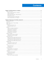
discharge-ESD protection...7 ESD field service kit ...8 Transporting sensitive components...9 After working inside your computer...9 Chapter 2: Removing and installing components 10 Recommended tools...10 Screw list...10 Major components of Vostro 5625...11 Base cover...13 Removing the - Dell Vostro 5625 | Service Manual - Page 4
the USB drive in Windows 67 Updating the BIOS from the F12 One-Time boot menu 68 Chapter 5: Troubleshooting...69 Handling swollen Lithium-ion batteries...69 Dell SupportAssist Pre-boot System Performance Check diagnostics 69 Running the SupportAssist Pre-Boot System Performance Check 70 Built-in - Dell Vostro 5625 | Service Manual - Page 5
System-diagnostic lights...71 Real-Time Clock (RTC Reset)...72 Recovering the operating system...73 Backup media and recovery options...73 WiFi power cycle...73 Drain residual flea power (perform hard reset)...73 Chapter 6: Getting help and contacting Dell 75 Contents 5 - Dell Vostro 5625 | Service Manual - Page 6
troubleshooting and repairs as authorized or directed by the Dell technical assistance team. Damage due to servicing that is not authorized by Dell is not covered by your warranty. See the safety instructions caution when handling Lithium-ion batteries in laptops. Swollen batteries should not be used - Dell Vostro 5625 | Service Manual - Page 7
any disassembly instructions. Observe the of getting electrocuted. Standby power Dell products with standby power must be is done through the use of a field service electrostatic discharge (ESD) kit. When connecting a not be obvious, such as intermittent problems or a shortened product life span - Dell Vostro 5625 | Service Manual - Page 8
damage to recognize and troubleshoot is the intermittent (also ESD mat, and the hardware is known as bonding. Use only Field Service kits with a wrist strap, mat, and bonding wire. Never use parts or parts to be returned to Dell, it is critical to place these parts in anti-static - Dell Vostro 5625 | Service Manual - Page 9
wrist strap and protective anti-static mat at all times when servicing Dell products. In addition, it is critical that technicians keep sensitive parts separate from all insulator parts while performing service and that they use anti-static bags for transporting sensitive components. Transporting - Dell Vostro 5625 | Service Manual - Page 10
2 Removing and installing components NOTE: The images in this document may differ from your computer depending on the configuration you ordered. Recommended tools The procedures in this document may require the following tools: ● Phillips screwdriver #0 ● Phillips screwdriver #1 ● Plastic scribe - Dell Vostro 5625 | Service Manual - Page 11
reader I/O board M2x3 M2x3 RJ-45 network port assembly M2x5 Touchpad Touchpad Display hinges M1.6x2 M2x1.8 M2.5x5 Quantity 2 1 2 3 3 2 5 Major components of Vostro 5625 The following image shows the major components of Vostro 5625. Screw image Removing and installing components 11 - Dell Vostro 5625 | Service Manual - Page 12
1. Base cover 2. Power-adapter port 3. Memory module 4. System board 5. Battery 6. Touchpad 7. Palm-rest and keyboard assembly 8. Left speaker 9. Display assembly 10. Right speaker 11. I/O board 12. Wireless-card bracket 13. Wireless card 14. M.2 2280 solid-state drive 15. M.2 2230 solid-state drive - Dell Vostro 5625 | Service Manual - Page 13
16. Coin-cell battery 17. System fan 18. Heat sink 19. Power button (with fingerprint reader - optional) 20. Power-button board NOTE: Dell provides a list of components and their part numbers for the original system configuration purchased. These parts are available according to warranty coverages - Dell Vostro 5625 | Service Manual - Page 14
14 Removing and installing components - Dell Vostro 5625 | Service Manual - Page 15
Steps 1. Remove the seven screws (M2x4) that secure the base cover to the palm-rest and keyboard assembly. 2. Loosen the two captive screws. 3. Using a plastic scribe, pry the base cover from the bottom left and continue to work on the sides to open the base cover. 4. Lift and slide the base cover - Dell Vostro 5625 | Service Manual - Page 16
16 Removing and installing components - Dell Vostro 5625 | Service Manual - Page 17
any kind to pry on or against the battery. ● Ensure any screws during the servicing of this product are not lost or misplaced, to prevent accidental puncture or damage to an instance, contact Dell technical support for assistance. See www.dell.com/contactdell. Removing and installing components 17 - Dell Vostro 5625 | Service Manual - Page 18
● Always purchase genuine batteries from www.dell.com or authorized Dell partners and resellers. ● Swollen batteries should not be used and should be replaced and disposed properly. For guidelines on how to handle and replace swollen - Dell Vostro 5625 | Service Manual - Page 19
Steps 1. Align the screw holes on the battery with the screw holes on the palm-rest and keyboard assembly. 2. Replace the three screws (M2x3) that secure the battery to the palm-rest and keyboard assembly. 3. Connect the battery cable to the system board. 4. Adhere the tape that secures the battery - Dell Vostro 5625 | Service Manual - Page 20
Steps 1. Peel the tape that secures the battery cable to the battery. 2. Disconnect the battery cable from the system board. 3. Remove the five screws (M2x3) that secure the battery to the palm-rest and keyboard assembly. 4. Lift the battery off the palm-rest and keyboard assembly. Installing the 4- - Dell Vostro 5625 | Service Manual - Page 21
Steps 1. Align the screw holes on the battery with the screw holes on the palm-rest and keyboard assembly. 2. Replace the five screws (M2x3) that secure the battery to the palm-rest and keyboard assembly. 3. Connect the battery cable to the system board. 4. Adhere the tape that secures the battery - Dell Vostro 5625 | Service Manual - Page 22
Steps 1. Lift the mylar covering the memory module. 2. Using your fingertips, carefully spread apart the securing-clips on each end of the memory-module slot until the memory module pops-up. 3. Remove the memory module from the memory-module slot on the system board. NOTE: Your computer has two - Dell Vostro 5625 | Service Manual - Page 23
Steps 1. Lift the mylar covering the memory-module slot. 2. Align the notch on the memory module with the tab on the memory-module slot on the system board. 3. Slide the memory module into the memory-module slot on the system board. 4. Press down on the memory module till the securing clips click, - Dell Vostro 5625 | Service Manual - Page 24
(shipped with the computer) with an M.2 2230 solid-state drive, a mounting bracket for the M.2 2230 solid-state drive is required. Please contact Dell support to purchase the mounting bracket for the M.2 2230 solid-state drive. The following image(s) indicate the location of the M.2 2230 solid-state - Dell Vostro 5625 | Service Manual - Page 25
(shipped with the computer) with an M.2 2230 solid-state drive, a mounting bracket for the M.2 2230 solid-state drive is required. Please contact Dell support to purchase the mounting bracket for the M.2 2230 solid-state drive. The following image(s) indicate the location of the M.2 2230 solid-state - Dell Vostro 5625 | Service Manual - Page 26
(shipped with the computer) with an M.2 2230 solid-state drive, a mounting bracket for the M.2 2230 solid-state drive is required. Please contact Dell support to purchase the mounting bracket for the M.2 2230 solid-state drive. The following image(s) indicate the location of the M.2 2280 solid-state - Dell Vostro 5625 | Service Manual - Page 27
(shipped with the computer) with an M.2 2230 solid-state drive, a mounting bracket for the M.2 2230 solid-state drive is required. Please contact Dell support to purchase the mounting bracket for the M.2 2230 solid-state drive. The following image(s) indicate the location of the M.2 2280 solid-state - Dell Vostro 5625 | Service Manual - Page 28
Steps 1. Align the notch on the M.2 2280 solid-state drive with the tab on the solid-state drive slot. 2. Slide the M.2 2280 solid-state drive into the solid-state drive slot 3. Replace the screw (M2x3) that secures the M.2 2280 solid-state drive to the palm-rest and keyboard assembly. Next steps 1. - Dell Vostro 5625 | Service Manual - Page 29
Steps 1. Remove the screw (M2x3) that secures the wireless-card bracket to the system board and palm-rest and keyboard assembly. 2. Lift the wireless-card bracket off the wireless card. 3. Disconnect the antenna cables from the wireless card. 4. Slide and remove the wireless card from the wireless- - Dell Vostro 5625 | Service Manual - Page 30
at an angle into the wireless-card slot. The following table provides the antenna-cable color scheme for the wireless card that is supported by your computer. Table 2. Antenna-cable color scheme Connectors on the wireless card Antenna-cable color Main White Auxiliary Black Silkscreen marking - Dell Vostro 5625 | Service Manual - Page 31
2. Follow the procedure in After working inside your computer. Fan Removing the fan Prerequisites 1. Follow the procedure in Before working inside your computer. 2. Remove the base cover. About this task The following image(s) indicate the location of the fan and provides a visual representation of - Dell Vostro 5625 | Service Manual - Page 32
Steps 1. Align the screw holes of the fan with screws on the palm-rest and keyboard assembly. 2. Replace the two screws (M2x3) that secure the fan to the palm-rest and keyboard assembly. 3. Connect the fan cable to the system board. Next steps 1. Install the base cover. 2. Follow the procedure in - Dell Vostro 5625 | Service Manual - Page 33
Steps 1. Disconnect the coin-cell battery cable from the I/O board. 2. Pry the coin-cell battery from the palm-rest and keyboard assembly. Installing the coin-cell battery Prerequisites If you are replacing a component, remove the existing component before performing the installation process. About - Dell Vostro 5625 | Service Manual - Page 34
Steps 1. Install the coin-cell battery into its slot on the palm-rest and keyboard assembly. 2. Connect the coin-cell battery cable to the I/O board. Next steps 1. Install the base cover. 2. Follow the procedure in After working inside your computer. Heat sink Removing the heatsink Prerequisites 1. - Dell Vostro 5625 | Service Manual - Page 35
the discrete Graphics Processing Unit (GPU). NOTE: This is the heatsink for your computer that supports integrated Graphics Processing Unit (GPU). Steps 1. In reverse sequential order (7>6>5>4>3>2>1), or (4>3>2>1), whichever is applicable, loosen the seven or four captive screws, whichever is - Dell Vostro 5625 | Service Manual - Page 36
following image(s) indicate the location of the heatsink and provides a visual representation of the installation procedure. NOTE: This is the heatsink for your computer that supports the discrete Graphics Processing Unit (GPU). 36 Removing and installing components - Dell Vostro 5625 | Service Manual - Page 37
NOTE: This is the heatsink for your computer that supports the integrated Graphics Processing Unit (GPU). Steps 1. Align the screw holes on the heat sink to the screw holes on the system board. 2. In sequential - Dell Vostro 5625 | Service Manual - Page 38
the clear adhesive tape. 6. Open the latch and disconnect the display cable from the system board. 7. Remove the display cable from the routing guides on the palm-rest and keyboard assembly. 8. Gently lift the palm-rest and keyboard assembly off the display assembly. 38 Removing and installing - Dell Vostro 5625 | Service Manual - Page 39
Installing the display assembly Prerequisites If you are replacing a component, remove the existing component before performing the installation process. About this task The following image(s) indicate the location of the display assembly and provides a visual representation of the installation - Dell Vostro 5625 | Service Manual - Page 40
the three screws (M2.5x5) that secure the right display hinge to the palm-rest and keyboard assembly. 7. Replace the display cable to the routing guides on the palm-rest and keyboard assembly. 8. Connect the display cable to the connector on the system board. 9. Close the latch and replace the clear - Dell Vostro 5625 | Service Manual - Page 41
Steps 1. Remove the three screws (M2.5x5) that secure the right-display hinge of the display assembly to the system board. 2. Open the right-display hinge at an angle of 90 degrees. 3. Remove the three screws (M2x5) that secure the RJ-45 Network Port assembly to the I/O board. 4. Lift the RJ-45 - Dell Vostro 5625 | Service Manual - Page 42
Installing the I/O board Prerequisites If you are replacing a component, remove the existing component before performing the installation process. About this task NOTE: A RJ-45 Network Port assembly for the I/O board is required. If you are replacing the I/O board, transfer the existing RJ-45 - Dell Vostro 5625 | Service Manual - Page 43
Steps 1. Align the screw holes on the I/O board with the screw holes on the system board and palm-rest and keyboard assembly. 2. Align the ports on the I/O board to the slots on the palm-rest and keyboard assembly. 3. Place the I/O board on the palm-rest and keyboard assembly. 4. Replace the two - Dell Vostro 5625 | Service Manual - Page 44
Steps 1. Open the latch of the touchpad connector on the system board and disconnect the touchpad cable from the system board. 2. Open the latch of the touchpad connector on the touchpad and disconnect the touchpad cable from the touchpad. 3. Peel off the adhesive tape from the touchpad bracket. 4. - Dell Vostro 5625 | Service Manual - Page 45
About this task NOTE: The wireless-card antennas are attached to the speakers as an assembly and cannot be separated for individual replacement. Services will replace the speakers and the wireless antennas as an assembly part. The following image(s) indicate the location of the speakers and provides - Dell Vostro 5625 | Service Manual - Page 46
. 3. Release the latch of the touchpad connector on the system board and disconnect the touchpad cable. 4. Remove the speakers cable from the routing guides on the palm-rest and keyboard assembly. 5. Disconnect the speaker cable. 6. Lift the speakers along with their cables off the palm-rest and - Dell Vostro 5625 | Service Manual - Page 47
Using the alignment posts, place the left and right speakers on the palm-rest and keyboard assembly. 2. Route the speaker cable through the routing guides on the palm-rest and keyboard assembly. 3. Adhere the tapes that secure the speaker cable to the palm-rest and keyboard assembly. 4. Connect the - Dell Vostro 5625 | Service Manual - Page 48
System board Removing the system board Prerequisites 1. Follow the procedure in Before working inside your computer. 2. Remove the base cover. 3. Remove the memory module. 4. Remove the M.2 2230 solid-state drive or M.2 2280 solid-state drive, whichever is applicable. 5. Remove the wireless card. 6. - Dell Vostro 5625 | Service Manual - Page 49
Steps 1. Remove the three screws (M2.5x5) that secure the right display hinge to the system board. 2. Open the right display hinge at an angle of 90 degrees. 3. Peel the clear adhesive tape of the display cable connector. 4. Open the latch and disconnect the display cable from the system board. 5. - Dell Vostro 5625 | Service Manual - Page 50
12. Peel the clear adhesive tape to lift the latch of the I/O board connector and disconnect the I/O board connector from the system board. 13. Disconnect the fan cable from the system board. 14. Remove the two screws (M2x1.8) that secure the system board to the palm-rest and keyboard assembly. 15. - Dell Vostro 5625 | Service Manual - Page 51
Steps 1. Install the system board at an angle and ensure that the ports are properly aligned with the port openings. 2. Place the system board on the palm-rest and keyboard assembly. 3. Align the screw holes on the system board with the screw holes on the palm-rest and keyboard assembly. 4. Replace - Dell Vostro 5625 | Service Manual - Page 52
12. Replace the two screws (M2x4) that secure the Type-C port-bracket to the system board. 13. Connect the power-adapter port cable to the system board and replace the adhesive tape on the cable. 14. Connect the display cable to the system board, close the latch of the display cable connector and - Dell Vostro 5625 | Service Manual - Page 53
2. Remove the screw (M2x3) that secures the power button to the palm-rest and keyboard assembly. 3. Lift the power button from the palm-rest and keyboard assembly. Installing the power button with optional fingerprint reader Prerequisites If you are replacing a component, remove the existing - Dell Vostro 5625 | Service Manual - Page 54
Power-adapter port Removing the power-adapter port Prerequisites 1. Follow the procedure in Before working inside your computer. 2. Remove the base cover. About this task The following image(s) indicate the location of the power-adapter port and provides a visual representation of the removal - Dell Vostro 5625 | Service Manual - Page 55
Steps 1. Place the power-adapter port into the slot on the palm-rest and keyboard assembly. 2. Adhere the tape that secures the power-adapter port cable to the system board. 3. Connect the power-adapter port cable to the system board. 4. Adhere the tape that covers the power-adapter port connector - Dell Vostro 5625 | Service Manual - Page 56
14. Remove the speakers. 15. Remove the touchpad. About this task The following image(s) indicate the location of the palm-rest and keyboard assembly and provides a visual representation of the removal procedure. Steps After performing the pre-requisites, you are left with the palm-rest and - Dell Vostro 5625 | Service Manual - Page 57
Steps Place the palm-rest and keyboard assembly on a flat and clean surface and perform the post-requisites to install the palm-rest and keyboard assembly. NOTE: The palm-rest and keyboard assembly includes the following components: ● Palm rest ● Keyboard ● Wireless antenna (2) Next steps 1. Install - Dell Vostro 5625 | Service Manual - Page 58
3 Drivers and downloads When troubleshooting, downloading or installing drivers it is recommended that you read the Dell Knowledge Based article, Drivers and Downloads FAQ 000123347. 58 Drivers and downloads - Dell Vostro 5625 | Service Manual - Page 59
4 BIOS setup CAUTION: Unless you are an expert computer user, do not change the settings in the BIOS Setup program. Certain changes can make your computer work incorrectly. NOTE: Depending on the computer and its installed devices, the items listed in this section may or may not be displayed. NOTE - Dell Vostro 5625 | Service Manual - Page 60
ownership date of the computer in MM/DD/YYYY format. BIOS Version Product Name Service Tag Asset Tag CPU Type CPU Speed CPU ID CPU Cache L1 Cache L2 the computer. Displays the system model name of the computer. Displays the service tag of the computer. Displays the asset tag of the computer. - Dell Vostro 5625 | Service Manual - Page 61
of the keyboard (option could be backlit or non-backlit). Table 5. System setup options-Advance menu Advance Multi-Cores Support Displays the support status for multi-cores. Virtualization Specify whether a Virtual Machine Monitor (VMM) can utilize the additional hardware capabilities provided - Dell Vostro 5625 | Service Manual - Page 62
Maintenance Data Wipe on next boot BIOS Recovery from Hard Drive BIOS Auto Recovery SupportAssist System Resolution Auto OS Recovery Threshold Support Assist OS Recovery Keyboard Illumination Keyboard Backlight with AC Controls the Power function on LID open action. Options are: ● Enabled (Default - Dell Vostro 5625 | Service Manual - Page 63
Table 5. System setup options-Advance menu (continued) Advance Internal Bluetooth Allows to Switch-on/switch-off the Bluetooth. Options are: ● Enabled (Default) ● Disabled Internal WLAN Allows to Switch-on/switch-off the Wireless Card. Options are: ● Enabled (Default) ● Disabled Media Card - Dell Vostro 5625 | Service Manual - Page 64
Path of the computer Operating System and allows to navigate and select the EFI file. File Browser Del Boot Option Windows Boot Manager: Displays the Dell Boot Path of the Default Boot Option.. 64 BIOS setup - Dell Vostro 5625 | Service Manual - Page 65
Table 7. System setup options-Boot menu (continued) Boot UEFI BOOT HDD1- Windows Boot Manager Displays the Device ID of the Secondary Storage of the computer. UEFI Onboard LAN IPv4 Displays the Device ID of the UEFI enabled Onboard IPv4 LAN controller. UEFI Onboard LAN IPv6 Displays the - Dell Vostro 5625 | Service Manual - Page 66
. Clearing BIOS (System Setup) and System passwords About this task To clear the system or BIOS passwords, contact Dell technical support as described at www.dell.com/contactdell. NOTE: For information on how to reset Windows or application passwords, refer to the documentation accompanying Windows - Dell Vostro 5625 | Service Manual - Page 67
.dell.com/support. 2. Click Product support. In the Search support box, enter the Service Tag of your computer, and then click Search. NOTE: If you do not have the Service Tag, use the SupportAssist feature to automatically identify your computer. You can also use the product ID or manually browse - Dell Vostro 5625 | Service Manual - Page 68
following: ● USB drive formatted to the FAT32 file system (key does not have to be bootable) ● BIOS executable file that you downloaded from the Dell Support website and copied to the root of the USB drive ● AC power adapter that is connected to the computer ● Functional computer battery to flash - Dell Vostro 5625 | Service Manual - Page 69
5 Troubleshooting Handling swollen Lithium-ion batteries Like most laptops, Dell laptops use lithium-ion batteries. approved recycling center. Contact Dell product support at https://www.dell.com/support for assistance and further instructions. ● Using a non-Dell or incompatible battery may increase - Dell Vostro 5625 | Service Manual - Page 70
more information, see https://www.dell.com/support/kbdoc/000180971. Running the EC) failures. NOTE: M-BIST can be manually initiated before POST (Power On Self Test). detected with the system board b. AMBER: Indicates a problem with the system board 3. If there is a failure Troubleshooting - Dell Vostro 5625 | Service Manual - Page 71
that helps you determine if the screen abnormality you are experiencing is an inherent problem with the LCD (screen) of the Dell laptop or with the video card (GPU) and PC settings. When you notice until the computer is turned off, indicating no memory or RAM is detected. Troubleshooting 71 - Dell Vostro 5625 | Service Manual - Page 72
and recommended solutions are intended for Dell service technicians to troubleshoot problems. You should only perform troubleshooting and repairs as authorized or directed by the Dell technical assistance team. Damage due to servicing that is not authorized by Dell is not covered by your warranty - Dell Vostro 5625 | Service Manual - Page 73
OS Recovery User's Guide at www.dell.com/serviceabilitytools. Click SupportAssist and then, click SupportAssist OS Recovery. Backup media and recovery options It is recommended to create a recovery drive to troubleshoot and fix problems that may occur with Windows. Dell proposes multiple options - Dell Vostro 5625 | Service Manual - Page 74
power adapter to your computer. 9. Turn on your computer. NOTE: For more information about performing a hard reset, see the knowledge base article 000130881 at www.dell.com/support. 74 Troubleshooting - Dell Vostro 5625 | Service Manual - Page 75
through videos, manuals and documents. In Windows search, type Contact Support, and press Enter. www.dell.com/support/windows Your Dell computer is uniquely identified by a Service Tag or Express Service Code. To view relevant support resources for your Dell computer, enter the Service Tag or
-
 1
1 -
 2
2 -
 3
3 -
 4
4 -
 5
5 -
 6
6 -
 7
7 -
8
-
9
-
10
-
11
-
12
-
13
-
14
-
15
-
16
-
17
-
18
-
19
-
20
-
21
-
22
-
23
-
24
-
25
-
26
-
27
-
28
-
29
-
30
-
31
-
32
-
33
-
34
-
35
-
36
-
37
-
38
-
39
-
40
-
41
-
42
-
43
-
44
-
45
-
46
-
47
-
48
-
49
-
50
-
51
-
52
-
53
-
54
-
55
-
56
-
57
-
58
-
59
-
60
-
61
-
62
-
63
-
64
-
65
-
66
-
67
-
68
-
69
-
70
-
71
-
72
-
73
-
74
-
75
 |
 |

Vostro 5625
Service Manual
Regulatory Model: P117F
Regulatory Type: P117F005
April 2021
Rev. A01