Dell XPS 13 7390 Service Manual - Page 13
Screw list, Screw image
 |
View all Dell XPS 13 7390 manuals
Add to My Manuals
Save this manual to your list of manuals |
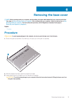
Page 13 highlights
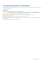
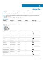
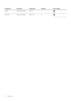
5 Screw list NOTE: When removing screws from a component, it is recommended to note the screw type, the quantity of screws, and then place them in a screw storage box. This is to ensure that the correct number of screws and correct screw type is restored when the component is replaced. NOTE: Some computers have magnetic surfaces. Ensure that the screws are not left attached to such surface when replacing a component. NOTE: Screw color may vary with the configuration ordered. Table 1. Screw list Component Secured to Screw type Quantity Screw image Keyboard Palm-rest assembly M1.6x1.5 29 Fingerprint-reader board Palm-rest assembly M1.6x1.5 1 NOTE: This component is only available on systems with fingerprint reader integrated on the power button. Power button Palm-rest assembly M1.4x1.7 2 System board Palm-rest assembly M1.6x2.5 10 Fans System board M1.6x3L 2 Speakers Palm-rest assembly M2x2 4 Heat sink System board M2x3 4 Headset port Palm-rest assembly M1.6x3 1 Display assembly Palm-rest assembly M2.5x4 4 Wireless antenna and System board M1.6x3L 1 camera cable bracket Display cable bracket System board M1.6x2.5 2 Solid-state drive shield System board M2x3L 1 and solid-state drive Battery Palm-rest assembly M2x2 4 Screw list 13
-
 1
1 -
2
-
3
-
4
-
5
-
6
-
7
-
 8
8 -
 9
9 -
 10
10 -
 11
11 -
 12
12 -
 13
13 -
 14
14 -
 15
15 -
 16
16 -
 17
17 -
 18
18 -
19
-
20
-
21
-
22
-
23
-
24
-
25
-
26
-
27
-
28
-
29
-
30
-
31
-
32
-
33
-
34
-
35
-
36
-
37
-
38
-
39
-
40
-
41
-
42
-
43
-
44
-
45
-
46
-
47
-
48
-
49
-
50
-
51
-
52
-
53
-
54
-
55
-
56
-
57
-
58
-
59
-
60
-
61
-
62
-
63
-
64
-
65
-
66
-
67
-
68
-
69
-
70
-
71
-
72
-
73
 |
 |
