Dell XPS M170 MXG051 XPS/Inspiron M170 Owners Manual - Page 99
Optical Drive, freely when you lift the display.
 |
View all Dell XPS M170 MXG051 manuals
Add to My Manuals
Save this manual to your list of manuals |
Page 99 highlights
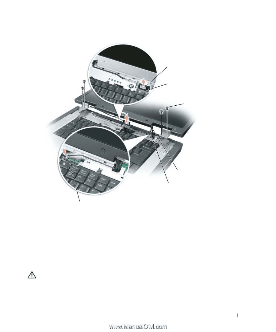
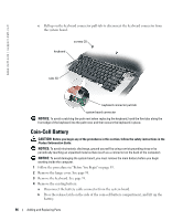
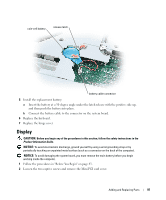
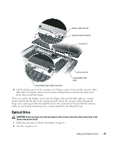
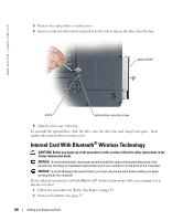
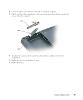
display cable pull-tab display cable connector screws (4) antenna cables customizable-light cable customizable-light cable connector 8 Lift the display away from the computer at a 90-degree angle. Ensure that the antenna cables, light cable, and display cable are free from the routing channels and that the cables move freely when you lift the display. When you replace the display, ensure that the display cable and the light cable are securely tucked underneath the tabs in the routing channels. Insert the antenna cables through the hinge cover opening and then through the hole in the system board. Ensure that the antenna cables are not twisted and that they are securely attached to the Mini PCI card. Optical Drive CAUTION: Before you begin any of the procedures in this section, follow the safety instructions in the Product Information Guide. 1 Follow the procedures in "Before You Begin" on page 83. 2 Turn the computer over. Adding and Replacing Parts 99
-
 1
1 -
2
-
3
-
4
-
5
-
6
-
7
-
8
-
9
-
10
-
11
-
12
-
13
-
14
-
15
-
16
-
17
-
18
-
19
-
20
-
21
-
22
-
23
-
24
-
25
-
26
-
27
-
28
-
29
-
30
-
31
-
32
-
33
-
34
-
35
-
36
-
37
-
38
-
39
-
40
-
41
-
42
-
43
-
44
-
45
-
46
-
47
-
48
-
49
-
50
-
51
-
52
-
53
-
54
-
55
-
56
-
57
-
58
-
59
-
60
-
61
-
62
-
63
-
64
-
65
-
66
-
67
-
68
-
69
-
70
-
71
-
72
-
73
-
74
-
75
-
76
-
77
-
78
-
79
-
80
-
81
-
82
-
83
-
84
-
85
-
86
-
87
-
88
-
89
-
90
-
91
-
92
-
93
-
 94
94 -
 95
95 -
 96
96 -
 97
97 -
 98
98 -
 99
99 -
 100
100 -
 101
101 -
 102
102 -
 103
103 -
 104
104 -
105
-
106
-
107
-
108
-
109
-
110
-
111
-
112
-
113
-
114
-
115
-
116
-
117
-
118
-
119
-
120
-
121
-
122
-
123
-
124
-
125
-
126
-
127
-
128
-
129
-
130
-
131
-
132
-
133
-
134
 |
 |