Dewalt DCGG571M1 Instruction Manual - Page 13
Variable Speed Trigger Switch Fig. 2, 4, Pressure Relief Valve Fig. 5, LED Worklight Fig. 2, 3 - grease gun
 |
View all Dewalt DCGG571M1 manuals
Add to My Manuals
Save this manual to your list of manuals |
Page 13 highlights
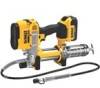
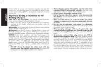
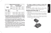
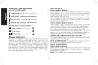
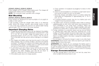
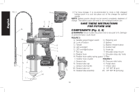
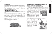
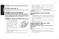
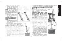
English INTENDED USE This grease gun is designed for professionally dispensing lubricant. DO NOT use under wet conditions or in presence of volatile flammable liquids or gases. This grease gun is a professional power tool. DO NOT let children come into contact with the tool. Supervision is required when inexperienced operators use this tool. LED Worklight (Fig. 2, 3) CAUTION: Do not stare into worklight. Serious eye injury could result. There is a LED worklight (D) located on the top cap (F). The worklight is activated when the trigger switch is depressed and when the LED worklight button (E) is in the ON position. When the LED worklight button is in the OFF position, the LED worklight will not turn on when the trigger is depressed. The worklight will automatically turn off 20 seconds after the trigger switch is released. If the trigger switch remains depressed, the worklight will remain on. NOTE: The worklight is for lighting the immediate work surface and is not intended to be used as a flashlight. FIG. 3 E D F Variable Speed Trigger Switch (Fig. 2, 4) LOCK-OFF BUTTON AND TRIGGER SWITCH Your grease gun is equipped with a lock-off button (B). To lock the trigger switch, press the lock-off button as shown in Figure 4. Always lock the trigger switch (A) when carrying or storing the tool to eliminate unintentional starting. The lock-off button is colored red to indicate when the switch is in its unlocked position. To unlock the trigger switch, press the FIG. 4 lock-off button as shown in Figure 4. Squeeze the trigger switch to turn the motor ON. Releasing the trigger switch turns the motor OFF. NOTE: The variable speed trigger switch B will give you added versatility. The further the trigger is depressed the higher the output of grease. WARNING: This tool has no provision to lock the switch in the ON position, and should never be locked ON by any other means. Pressure Relief Valve (Fig. 5) The pressure relief valve (W) is set at FIG. 5 the factory to relieve pressure X above 10,000 psi (690 bar). Grease coming out of the pressure relief valve indicates a clog in the fitting, line or bearing. Any of these W conditions must be corrected before proceeding. Y AA Z 11
-
 1
1 -
2
-
3
-
4
-
5
-
6
-
7
-
 8
8 -
 9
9 -
 10
10 -
 11
11 -
 12
12 -
 13
13 -
 14
14 -
 15
15 -
 16
16 -
 17
17 -
 18
18 -
19
-
20
-
21
-
22
-
23
-
24
-
25
-
26
-
27
-
28
-
29
-
30
-
31
-
32
-
33
-
34
-
35
-
36
-
37
-
38
-
39
-
40
-
41
-
42
-
43
-
44
-
45
-
46
-
47
-
48
-
49
-
50
-
51
-
52
-
53
-
54
-
55
-
56
-
57
-
58
-
59
-
60
-
61
-
62
-
63
-
64
-
65
-
66
-
67
-
68
 |
 |