Dewalt DCH273B Instruction Manual - Page 12
Side Handle Fig. 2, Trigger Switch Fig. 2, Utility Hook Fig. 3
 |
View all Dewalt DCH273B manuals
Add to My Manuals
Save this manual to your list of manuals |
Page 12 highlights
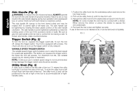
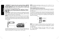
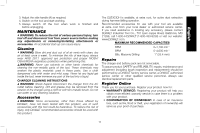
English Side Handle (Fig. 2) WARNING: To reduce the risk of personal injury, ALWAYS operate the tool with the side handle (A) properly installed. Failure to do so may result in the side handle slipping during tool operation and subsequent loss of control. Hold tool with both hands to maximize control. The side handle (A) clamps to the front barrel (collar) and may be rotated 360° to permit right-or left-hand use. The side handle can be tightened by rotating the black plastic portion of the side handle clockwise. The side handle must be tightened sufficiently to resist the twisting action of the tool if the accessory binds or stalls. Be sure to grip the side handle at the far end to control the tool during a stall. To loosen side handle, rotate counterclockwise. Trigger Switch (Fig. 2) To turn the tool on, squeeze the trigger switch (B). To turn the tool off, release the trigger switch. Your tool is equipped with a brake. The chuck will stop as soon as the trigger switch is fully released. VARIABLE SPEED TRIGGER SWITCH The variable speed trigger switch enables you to select the best speed for a particular application. The farther you squeeze the trigger switch, the faster the tool will operate. For maximum tool life, use variable speed only for starting holes or fasteners. NOTE: Continuous use in variable speed range is not recommended. It may damage the trigger switch and should be avoided. Utility Hook (Fig. 3) A utility hook is fitted to the left side of the tool. To extend the utility hook pull it out from the side of the tool. To store the utility hook push it back flush with the side of the tool. The utility hook (J) and can be positioned to the left or right of the tool to accommodate left or righthanded users. 1. Position the utility hook into the extended position and remove the hex head screw. 2. Pull out the utility hook (J) until it is free from unit. 3. Reinsert the utility hook into the desired side and push it into the slot. NOTE: On some models the slot may be covered with a sticker. Either remove the sticker or pierce the sticker to expose the slot underneath. 4. Re-insert the hex screw and tighten securely. If use of the hook is not desired at all, it can be removed completely. FIG. 3 J 10
-
 1
1 -
2
-
3
-
4
-
5
-
6
-
 7
7 -
 8
8 -
 9
9 -
 10
10 -
 11
11 -
 12
12 -
 13
13 -
 14
14 -
 15
15 -
 16
16 -
 17
17 -
18
-
19
-
20
-
21
-
22
-
23
-
24
-
25
-
26
-
27
-
28
-
29
-
30
-
31
-
32
-
33
-
34
-
35
-
36
-
37
-
38
-
39
-
40
-
41
-
42
-
43
-
44
-
45
-
46
-
47
-
48
-
49
-
50
-
51
-
52
-
53
-
54
-
55
-
56
-
57
-
58
-
59
-
60
 |
 |
