Dewalt DCH273B Instruction Manual - Page 13
Worklight Fig. 6, OPERATION, Mode Selector Fig. 4, Forward/Reverse Control Button Fig. 2, 5
 |
View all Dewalt DCH273B manuals
Add to My Manuals
Save this manual to your list of manuals |
Page 13 highlights
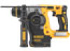
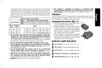
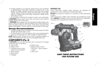
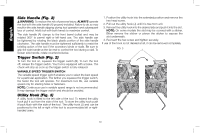
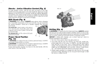
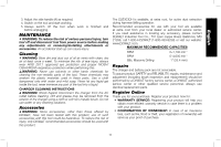
English Mode Selector (Fig. 4) CAUTION: Do not change to drill or hammerdrill mode with a chisel bit in the chuck. Personal injury and damage to tool may result. CAUTION: Never change the mode while the unit is running. For straight drilling, rotate the mode FIG. 4 selector (D) until the arrow points to the drill L bit symbol (J). For rotary hammer mode, align the arrow with the rotary hammer symbol (K). For chipping mode, align arrow D with the chipping symbol (L). NOTE: The mode selector (D) must be in drill, hammer or chipping mode at all times. There are no operable positions K J in between. Forward/Reverse Control Button (Fig. 2, 5) A forward/reverse control button (C) determines the direction of bit rotation and also serves as a lock-off button. To select forward rotation, release the trigger switch (B) and depress the forward/reverse control button on the right side of the tool. To select reverse, depress the forward/reverse control button on the left side of the tool. The center position of the control button locks the tool in the off position. When changing the position of the control button, be sure the trigger is released. NOTE: The first time the tool is run after changing the direction of rotation, you may hear a click on start up. This is normal and does not indicate a problem. FIG. 5 C UNLOCKED, FORWARD LOCKED UNLOCKED, REVERSE Worklight (Fig. 6) There is a worklight (F) located on the front FIG. 6 of the tool. The worklight is activated when the trigger switch is depressed, and will automatically turn off 20 seconds after the trigger switch is released. If the trigger F switch remains depressed, the worklight will remain on. NOTE: The worklight is for lighting the immediate work surface and is not intended to be used as a flashlight. OPERATION WARNING: To reduce the risk of serious personal injury, turn tool off and disconnect tool from power source before making any adjustments or removing/installing attachments or accessories. An accidental start-up can cause injury. WARNING: To reduce the risk of personal injury, ALWAYS ensure workpiece is anchored or clamped firmly. If drilling thin material, use a wood "back-up" block to prevent damage to the material. 11
-
 1
1 -
2
-
3
-
4
-
5
-
6
-
7
-
 8
8 -
 9
9 -
 10
10 -
 11
11 -
 12
12 -
 13
13 -
 14
14 -
 15
15 -
 16
16 -
 17
17 -
 18
18 -
19
-
20
-
21
-
22
-
23
-
24
-
25
-
26
-
27
-
28
-
29
-
30
-
31
-
32
-
33
-
34
-
35
-
36
-
37
-
38
-
39
-
40
-
41
-
42
-
43
-
44
-
45
-
46
-
47
-
48
-
49
-
50
-
51
-
52
-
53
-
54
-
55
-
56
-
57
-
58
-
59
-
60
 |
 |