Dewalt DCT412S1 Instruction Manual - Page 11
ASSEMBLY, Screen Fig. 4, Camera Cable Fig. 5
 |
View all Dewalt DCT412S1 manuals
Add to My Manuals
Save this manual to your list of manuals |
Page 11 highlights
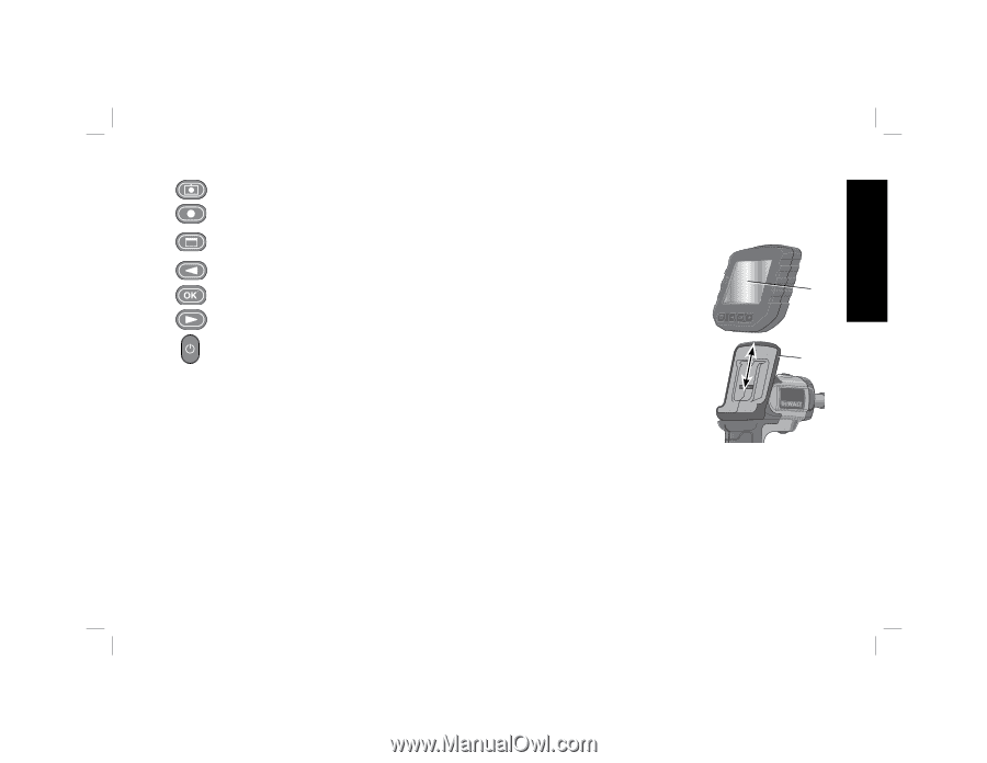
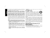
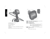
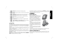
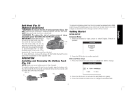
English L. Camera: Press this button for taking a photo. M. Record: Press this button to start and stop recording a video. N. Main Menu: Press this button to show a list of options for operating the inspection camera or to exit a screen. O. Back Arrow: Press this button to navigate backward. P. OK: Press this button to save changes. Q. Forward Arrow: Press this button to navigate forward. R. Power indicator for the handle set: When the green light is on it indicates that the handle set is on. S. Reset button INTENDED USE The inspection camera is designed to play real-time video while looking into walls and/or tight spaces. With a micro SD card (sold separately), the tool can then take photos or record videos for documentation purposes. Photos are saved in JPG format and videos are saved as AVI. This DEWALT inspection camera is compatible with micro SD memory cards up to 16 gigabytes. Applications consist of automotive inspection, plumbing inspection, HVAC inspection or cable routing. Read the entire manual before using this inspection camera. DO NOT use in presence of flammable liquids or gases. The camera cable extension is waterproof up to the camera connector. DO NOT USE the handle set under wet conditions. The inspection camera is a professional tool. DO NOT let children come into contact with the tool. Supervision is required when inexperienced operators use this tool. ASSEMBLY FIG. 4 Screen (Fig. 4) When the screen is attached to the handle set with a battery, it will receive a charge from the battery. Ensure the E screen is fully charged before use. When the screen is disengaged from the handle set, a battery icon appears in the upper left corner. This icon also displays the current charge of the screen. G To install the screen (E) into the handle set (G), align the screen with the rails on the handle set and slide it firmly into the handle until you hear the lock snap into place. To remove the screen from the handle set, firmly slide the screen up from the tool handle. The screen can be turned on and viewed when it is not attached to the handle set, allowing easier maneuverability of the camera. Camera Cable (Fig. 5) Align the camera cable with the camera connector (D). Push in and turn the connector counterclockwise (camera screen facing you) to firmly attach. 9
-
 1
1 -
2
-
3
-
4
-
5
-
 6
6 -
 7
7 -
 8
8 -
 9
9 -
 10
10 -
 11
11 -
 12
12 -
 13
13 -
 14
14 -
 15
15 -
 16
16 -
17
-
18
-
19
-
20
-
21
-
22
-
23
-
24
-
25
-
26
-
27
-
28
-
29
-
30
-
31
-
32
-
33
-
34
-
35
-
36
-
37
-
38
-
39
-
40
-
41
-
42
-
43
-
44
-
45
-
46
-
47
-
48
-
49
-
50
-
51
-
52
-
53
-
54
-
55
-
56
-
57
-
58
-
59
-
60
-
61
-
62
-
63
-
64
 |
 |