EVGA 113-YW-E115-TR User Manual - Page 24
CMOS Clear Button
 |
View all EVGA 113-YW-E115-TR manuals
Add to My Manuals
Save this manual to your list of manuals |
Page 24 highlights
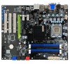
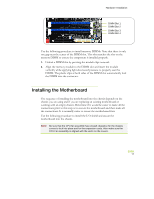
Hardware Installation ‰ Power Connections ¾ 24-pin ATX power (PW1) ¾ 8-pin ATX 12V power (PW12) ‰ Internal Headers ¾ Front panel ¾ Speaker ¾ USB Headers ¾ Audio ¾ COM ‰ FDD ‰ IDE ‰ Serial ATA II ‰ Chassis Fans ‰ Expansion slots ‰ CMOS Clear Button See Figure 1 on page 6 to locate the connectors and Button referenced in the following procedure. EVGA 13
-
 1
1 -
2
-
3
-
4
-
5
-
6
-
7
-
8
-
9
-
10
-
11
-
12
-
13
-
14
-
15
-
16
-
17
-
18
-
 19
19 -
 20
20 -
 21
21 -
 22
22 -
 23
23 -
 24
24 -
 25
25 -
 26
26 -
 27
27 -
 28
28 -
 29
29 -
30
-
31
-
32
-
33
-
34
-
35
-
36
-
37
-
38
-
39
-
40
-
41
-
42
-
43
-
44
-
45
-
46
-
47
-
48
-
49
-
50
-
51
-
52
-
53
-
54
-
55
-
56
-
57
-
58
-
59
-
60
-
61
-
62
-
63
-
64
-
65
-
66
-
67
-
68
-
69
-
70
-
71
-
72
-
73
-
74
-
75
-
76
-
77
-
78
-
79
-
80
-
81
-
82
-
83
-
84
-
85
 |
 |

Hardware Installation
EVGA
13
Power Connections
24-pin ATX power (
PW1
)
8-pin ATX 12V power (
PW12
)
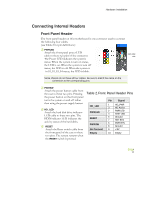
Internal Headers
Front panel
Speaker
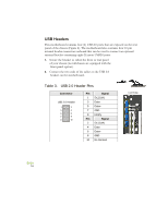
USB Headers
Audio
COM
FDD
IDE
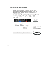
Serial ATA II
Chassis Fans
Expansion slots
CMOS Clear Button
See Figure 1 on page 6 to locate the connectors and Button referenced in the
following procedure.