EVGA 113-YW-E115-TR User Manual - Page 32
FDD Connector, Expansion Slots
 |
View all EVGA 113-YW-E115-TR manuals
Add to My Manuals
Save this manual to your list of manuals |
Page 32 highlights
Hardware Installation COM1 The motherboard kit provides an additional serial COM header for your machine. Connect one side of a switching cable to the header and then attach the serial COM device to the other side of the cable. FDD Connector The motherboard supports a standard 360K, 720K, 1.2M, 1.44m, and a 2.88M floppy disk drive (FDD). Expansion Slots This motherboard contains six expansion slots, three PCI Express slots and three PCI slots. For a full list of PCI Express x16 graphics card supported by this motherboard, go to www.nvidia.com/estore. 1 2 3 4 5 6 1 - PCI slot 3 2 - PCI slot 2 3 - PCI slot 1 4 - PCI-E x16 slot 5 - PCI-E x1 slot 6 - PCI-E x1 slot EVGA 21
-
 1
1 -
2
-
3
-
4
-
5
-
6
-
7
-
8
-
9
-
10
-
11
-
12
-
13
-
14
-
15
-
16
-
17
-
18
-
19
-
20
-
21
-
22
-
23
-
24
-
25
-
26
-
 27
27 -
 28
28 -
 29
29 -
 30
30 -
 31
31 -
 32
32 -
 33
33 -
 34
34 -
 35
35 -
 36
36 -
 37
37 -
38
-
39
-
40
-
41
-
42
-
43
-
44
-
45
-
46
-
47
-
48
-
49
-
50
-
51
-
52
-
53
-
54
-
55
-
56
-
57
-
58
-
59
-
60
-
61
-
62
-
63
-
64
-
65
-
66
-
67
-
68
-
69
-
70
-
71
-
72
-
73
-
74
-
75
-
76
-
77
-
78
-
79
-
80
-
81
-
82
-
83
-
84
-
85
 |
 |

Hardware Installation
EVGA
21
COM1
The motherboard kit provides an additional serial COM header for your
machine. Connect one side of a switching cable to the header and then attach
the serial COM device to the other side of the cable.
FDD Connector
The motherboard supports a standard 360K, 720K, 1.2M, 1.44m, and a 2.88M
floppy disk drive (FDD).
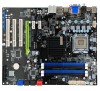
Expansion Slots
This motherboard contains six expansion slots, three PCI Express slots and
three PCI slots. For a full list of PCI Express x16 graphics card supported by
this motherboard, go to
www.nvidia.com/estore
.
1
– PCI slot 3
2
– PCI slot 2
3
– PCI slot 1
4
– PCI-E x16 slot
5
– PCI-E x1 slot
6
– PCI-E x1 slot
6
5
3
1
4
2