EVGA 113-YW-E115-TR User Manual - Page 29
USB Headers
 |
View all EVGA 113-YW-E115-TR manuals
Add to My Manuals
Save this manual to your list of manuals |
Page 29 highlights
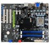
USB Headers This motherboard contains four (4) USB 2.0 ports that are exposed on the rear panel of the chassis (Figure 2). The motherboard also contains four 10-pin internal header connectors onboard that can be used to connect an optional external bracket containing eight (8) more USB2.0 ports. 1. Secure the bracket to either the front or rear panel of your chassis (not all chassis are equipped with the front panel option). 2. Connect the two ends of the cables to the USB 2.0 headers on the motherboard. Table 3. USB 2.0 Header Pins Connector USB 2.0 Header Pin Signal 1 5V_DUAL 3 Data- 5 Data+ 7 GND 9 Empty Pin Signal 2 5V_DUAL 4 Data- 6 Data+ 8 GND 10 No Connect Card Edge EVGA 18
-
 1
1 -
2
-
3
-
4
-
5
-
6
-
7
-
8
-
9
-
10
-
11
-
12
-
13
-
14
-
15
-
16
-
17
-
18
-
19
-
20
-
21
-
22
-
23
-
 24
24 -
 25
25 -
 26
26 -
 27
27 -
 28
28 -
 29
29 -
 30
30 -
 31
31 -
 32
32 -
 33
33 -
 34
34 -
35
-
36
-
37
-
38
-
39
-
40
-
41
-
42
-
43
-
44
-
45
-
46
-
47
-
48
-
49
-
50
-
51
-
52
-
53
-
54
-
55
-
56
-
57
-
58
-
59
-
60
-
61
-
62
-
63
-
64
-
65
-
66
-
67
-
68
-
69
-
70
-
71
-
72
-
73
-
74
-
75
-
76
-
77
-
78
-
79
-
80
-
81
-
82
-
83
-
84
-
85
 |
 |

EVGA
18
USB Headers
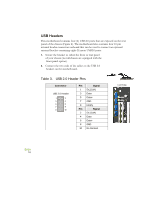
This motherboard contains four (4) USB 2.0 ports that are exposed on the rear
panel of the chassis (Figure 2). The motherboard also contains four 10-pin
internal header connectors onboard that can be used to connect an optional
external bracket containing eight (8) more USB2.0 ports.
1.
Secure the bracket to either the front or rear panel
of your chassis (not all chassis are equipped with the
front panel option).
2.
Connect the two ends of the cables to the USB 2.0
headers on the motherboard.
Table 3.
USB 2.0 Header Pins
Connector
Pin
Signal
USB 2.0 Header
1
5V_DUAL
3
Data-
5
Data+
7
GND
9
Empty
Pin
Signal
2
5V_DUAL
4
Data-
6
Data+
8
GND
10
No Connect
Card Edge