Electrolux EI30EF4CQS Installation Instructions (English, Spanish, French) - Page 7
Connect the range to the gas supply
 |
View all Electrolux EI30EF4CQS manuals
Add to My Manuals
Save this manual to your list of manuals |
Page 7 highlights
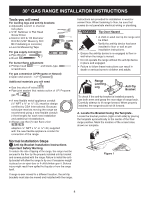
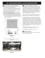
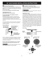
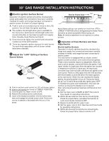
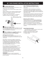
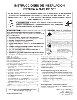
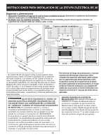
30" GAS RANGE INSTALLATION INSTRUCTIONS 4 Connect the range to the gas supply Important: Remove all packing material and literature from range before connecting gas and electrical supply. Note: To prevent leaks, put pipe joint sealant on all external pipe threads. Do not allow regulator to rotate on pipe when tightening fittings. Connection to Pressure Regulator The regulator is already installed on the appliance. Do not make the connection too tight. The regulator is die cast. Overtightening may crack the regulator resulting in a gas leak and possible fire or explosion. Figure 5c Figure 5b A. Install an external manual gas shut-off valve to gas supply line in an accessible location outside of the range. Be sure you know where and how to shut off the gas supply to the range. B. Install ½" flare union adapter to unit shut-off valve using NO MORE THAN 15ft./lbs. of torque. NOTE: Be sure to stabilize the right side of the unit shut-off valve with adjustable wrench before tightening ANY fittings to the unit shut-off valve. C. Tighten the gas flexible connector and/or appliance conduit to flare union on the left side of the unit shut-off valve using NO MORE THAN 15ft./ lbs. of torque. Be sure to stabilize the ½" flare union adapter with an adjustable wrench before tightening the gas flexible connector and/or appliance conduit. D. Install flare union adapter to external shut-off valve. E. Attach the gas flexible connector with the flare union on shut-off valve. F. Make sure both shut-off valves are in the "ON" position. G. Form the gas flexible connector as shown on figure 5c. This will prevent the flexible connector from pinching or blocking the unit when you will push it back in its final position. H. Check for leaks. Turn the gas supply on to the range and use a liquid leak detector (or soap and water) at all joints and conduits to check for leaks in the system. leaks. Do not use a flame to check for gas Note: The purpose of forming the gas flexible connector is to position it in a way that will not block the unit or get pinched in it's final position. If your unit in place is not against the wall as you wish, check behind the range and place the gas flexible connector to avoid the range being blocked or the gas flexible connector being pinched. Checking Manifold Gas Pressure Disconnect this range and its individual manual shutoff valve from the gas supply piping system during any pressure testing of that system at test pressures greater than 14" water column pressure (approximately ½" psig). The appliance must be isolated from the gas supply piping system by closing its individual manual shutoff valve during any pressure testing of the gas supply piping system at test pressures equal to or less than 14" water column pressure (approximately ½" psig). If it should be necessary to check the manifold gas pressure, connect manometer (water gauge) or other pressure device to the top burner right rear orifice. Using a rubber hose with inside diameter of approximately ¼" hold tubing down tight over orifice. Turn burner valve on. For accurate pressure check have at least two (2) other top burners burning. Be sure the gas supply (inlet) pressure is at least one inch above specified range manifold pressure. The gas supply pressure should never be over 14" water column. When properly adjusted for Natural Gas manifold pressure is 4" (For LP/Propane Gas the manifold pressure is 10") 7
-
 1
1 -
 2
2 -
 3
3 -
 4
4 -
 5
5 -
 6
6 -
 7
7 -
 8
8 -
 9
9 -
 10
10 -
 11
11 -
 12
12 -
13
-
14
-
15
-
16
-
17
-
18
-
19
-
20
-
21
-
22
-
23
-
24
-
25
-
26
-
27
-
28
-
29
-
30
-
31
-
32
 |
 |
