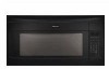
Electrolux EI30MH55GB Service Manual - Page 25
Touch Control Panel Assembly
 |
UPC - 012505558610
View all Electrolux EI30MH55GB manuals
Add to My Manuals
Save this manual to your list of manuals |
Page 25 highlights
TOUCH CONTROL PANEL ASSEMBLY OUTLINE OF TOUCH CONTROL PANEL EI30MH55GSA EI30MH55GBA EI30MH55GWA The touch control section consists of the following units as shown in the touch control panel circuit. (1) Key Unit (2) Control Unit (The Control unit consists of LSI Unit and Power U nit) The principal functions of these units and the signals communicated among them are explained below. Key Unit The key unit is composed of a matrix, signals generated in the LSI are sent to the key unit through P20, P21, P22, P23, P24, P25, P26 and P27. When a key pad is touched, a signal is completed through the key unit and passed back to the LSI through P43, P44, P45 and P46 to perform the function that was requested. Control Unit Control unit consists of LSI, power source circuit, synchronizing signal circuit, reset circuit, buzzer circuit, relay circuit indicator circuit, back light circuit and humidity sensor circuit. 1) LSI This LSI controls the key strobe signal, relay driving signal for oven function and indicator signal. 2) Power Source Circuit This circuit generates voltages necessary for the control unit from the AC line voltage. In addition, the synchronizing signal is available in order to compose a basic standard time in the clock circuit. Symbol VC Voltage -5.0V Application LSI(IC1) 3) Synchronizing Signal Circuit The power source synchronizing signal is available in order to compose a basic standard time in the clock circuit.It incorporates a very small error because it works on commercial frequency. 4) Reset Circuit A circuit to generate a signals which resetting the LSI to the initial state when power is applied. 5) Buzzer Circuit The buzzer is responds to signals from the LSI to emit audible sounds (key touch sound and completion sound). 6) Stop Switch A switch to inform the LSI if the door is open or closed. 7) Relay Circuit To drive the inverter unit, fan motor, stirrer motor, hood motor, and light the oven lamp and hood lamp. 8) Indicator Circuit This circuit consists of 25 segments and 4 common electrodes using a Light Crystal Display. 9) Back Light Circuit A circuit to drive the back light (Light emitting diodes LD1-LD5). 10) Humidity Sensor Circuit This circuit detects moisture of the cooking food to allow its automatic cooking. 11) Inverter Unit Control Circuit This is the circuit to control inverter unit. 25
-
 1
1 -
2
-
3
-
4
-
5
-
6
-
7
-
8
-
9
-
10
-
11
-
12
-
13
-
14
-
15
-
16
-
17
-
18
-
19
-
 20
20 -
 21
21 -
 22
22 -
 23
23 -
 24
24 -
 25
25 -
 26
26 -
 27
27 -
 28
28 -
 29
29 -
 30
30 -
31
-
32
-
33
-
34
-
35
-
36
-
37
-
38
-
39
-
40
-
41
-
42
-
43
-
44
-
45
-
46
-
47
-
48
-
49
-
50
-
51
-
52
 |
 |
