Epson C31C636834 Technical Reference - Page 19
Caution, Warning
 |
View all Epson C31C636834 manuals
Add to My Manuals
Save this manual to your list of manuals |
Page 19 highlights
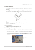
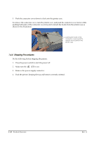
TM-T88IV Technical Reference Guide 1.3.3 Power Switch The power switch is located at the bottom right front of the printer. (Refer to "Printer part names" (page 1-3).) Turn the printer on or off. The marks on the switch (0 = on / 1 = off) indicate the printer switch position. CAUTION: Before turning on the printer be sure to check that the AC adapter is connected to the power supply. 1.3.4 Connectors All cables are connected to the connector panel on the lower rear of the printer. FG FG DK DC24V Interface connector Drawer kick-out connector Power supply connector Figure 1-2 Connector panel ❏ Drawer kick-out connector for connecting the cash drawer ❏ Power supply connector for connecting the power supply unit ❏ Interface connector to connect the printer to the host computer interface (serial, parallel, etc.) Note: The picture above shows a serial interface model. For details on the various interfaces and how to connect the power supply connector and cash drawer, see "Connecting Power Supply Unit and Cash Drawer" (page 2-15) and "Connecting the Printer to the Host Computer" (page 2-8). 1.4 Handling the Printer WARNING: Do not open the printer cover during printing. Doing so may damage the printer. Do not touch the manual cutter with your hands when installing or replacing roll paper. The manual cutter is sharp and may cause an injury. Rev. A Product Overview 1-5
-
 1
1 -
2
-
3
-
4
-
5
-
6
-
7
-
8
-
9
-
10
-
11
-
12
-
13
-
 14
14 -
 15
15 -
 16
16 -
 17
17 -
 18
18 -
 19
19 -
 20
20 -
 21
21 -
 22
22 -
 23
23 -
 24
24 -
25
-
26
-
27
-
28
-
29
-
30
-
31
-
32
-
33
-
34
-
35
-
36
-
37
-
38
-
39
-
40
-
41
-
42
-
43
-
44
-
45
-
46
-
47
-
48
-
49
-
50
-
51
-
52
-
53
-
54
-
55
-
56
-
57
-
58
-
59
-
60
-
61
-
62
-
63
-
64
-
65
-
66
-
67
-
68
-
69
-
70
-
71
-
72
-
73
-
74
-
75
-
76
-
77
-
78
-
79
-
80
-
81
-
82
-
83
-
84
-
85
-
86
-
87
-
88
-
89
-
90
 |
 |
