Epson C31C636834 Technical Reference - Page 27
DIP Switch Functions
 |
View all Epson C31C636834 manuals
Add to My Manuals
Save this manual to your list of manuals |
Page 27 highlights
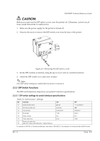
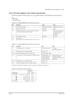
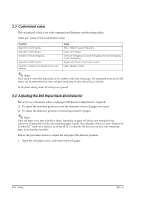
TM-T88IV Technical Reference Guide CAUTION: Before you remove the DIP switch cover, turn the printer off. Otherwise, a short-circuit may cause the printer to malfunction. 1. Make sure the power supply for the printer is turned off. 2. Unscrew the screw to remove the DIP switch cover from the base of the printer. DSW1 DSW2 Figure 2-9 Removing the DIP switch cover 3. Set the DIP switches as desired, using the tip of a tool, such as a small screwdriver. 4. Attach the DIP switch cover, and screw in place. Note: New DIP switch settings are enabled after the printer is turned on. 2.2.2 DIP Switch Functions The DIP switch functions depend on your printer's interface specifications. 2.2.2.1 DIP switch settings for serial interface specifications Table 2-2 Switch bank 1 settings SW Function 1-1 Data receive error 1-2 Receive buffer size 1-3 Handshake 1-4 Bit length 1-5 Parity check 1-6 Parity selection 1-7, Baud rate selection 1-8 (See the "Baud rate selection" tables below.) ON Ignore 45 bytes XON/XOFF 7 bits Yes Even OFF "?" is printed * 4KB * DTR/DSR * 8 bits * No * Odd * For details on DIP SW1-2: Receive buffer size, also refer to DIP SW2-5: Cancellation of receive buffer full BUSY state. Rev. A Setup 2-3
-
 1
1 -
2
-
3
-
4
-
5
-
6
-
7
-
8
-
9
-
10
-
11
-
12
-
13
-
14
-
15
-
16
-
17
-
18
-
19
-
20
-
21
-
 22
22 -
 23
23 -
 24
24 -
 25
25 -
 26
26 -
 27
27 -
 28
28 -
 29
29 -
 30
30 -
 31
31 -
 32
32 -
33
-
34
-
35
-
36
-
37
-
38
-
39
-
40
-
41
-
42
-
43
-
44
-
45
-
46
-
47
-
48
-
49
-
50
-
51
-
52
-
53
-
54
-
55
-
56
-
57
-
58
-
59
-
60
-
61
-
62
-
63
-
64
-
65
-
66
-
67
-
68
-
69
-
70
-
71
-
72
-
73
-
74
-
75
-
76
-
77
-
78
-
79
-
80
-
81
-
82
-
83
-
84
-
85
-
86
-
87
-
88
-
89
-
90
 |
 |
