Epson FX-286e User Manual - Page 159
Environment, Parallel Interface, Technical Specifications
 |
View all Epson FX-286e manuals
Add to My Manuals
Save this manual to your list of manuals |
Page 159 highlights
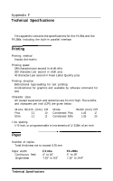
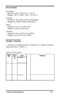
Environment Temperature Operation: 40°F to 95°F (5 C" to 35 Co) Storage: -25°F to 150°F (-30 C" to 65 Co) Humidity Operation: 10% to 80% without condensation Storage: 5% to 85% without condensation Shock Operation: Up to 1 G within 1ms Storage: Up to 2 G within 1ms Vibration Operation: Up to 0.25 G at up to 55Hz Storage: Up to 0.5 G at up, to 55Hz Parallel Interface Connector pin assignments and a description of respective interface signals are shown in Table F- 1, Table F-I. Pins and signals Signal Return - Pi-n . Pin 1 19 Signal STROBE 2 20 DATA 1 3 2 1 DATA 2 4 22 DATA 3 5 2 3 DATA 4 6 2 4 DATA 5 7 2 5 DATA 6 8 26 DATA 7 9 2 7 DATA 8 10 28 ACKNLG Description IN STROBE pulse to read data in. Pulse tiidth must be more than 0.5 microseconds at the receiving terminal. IN These signals represent information of IN the 1 st to 8th bits of parallel data, IN respectively. Each signal is at HIGH I N level when data is logical 1 and LOW IN when it is logical 0. IN IN OUT Approximately 12-microsecond pulse LOW indicates that data has been received and that the printer is ready to accept more data. Technical Specifications F-3
-
 1
1 -
2
-
3
-
4
-
5
-
6
-
7
-
8
-
9
-
10
-
11
-
12
-
13
-
14
-
15
-
16
-
17
-
18
-
19
-
20
-
21
-
22
-
23
-
24
-
25
-
26
-
27
-
28
-
29
-
30
-
31
-
32
-
33
-
34
-
35
-
36
-
37
-
38
-
39
-
40
-
41
-
42
-
43
-
44
-
45
-
46
-
47
-
48
-
49
-
50
-
51
-
52
-
53
-
54
-
55
-
56
-
57
-
58
-
59
-
60
-
61
-
62
-
63
-
64
-
65
-
66
-
67
-
68
-
69
-
70
-
71
-
72
-
73
-
74
-
75
-
76
-
77
-
78
-
79
-
80
-
81
-
82
-
83
-
84
-
85
-
86
-
87
-
88
-
89
-
90
-
91
-
92
-
93
-
94
-
95
-
96
-
97
-
98
-
99
-
100
-
101
-
102
-
103
-
104
-
105
-
106
-
107
-
108
-
109
-
110
-
111
-
112
-
113
-
114
-
115
-
116
-
117
-
118
-
119
-
120
-
121
-
122
-
123
-
124
-
125
-
126
-
127
-
128
-
129
-
130
-
131
-
132
-
133
-
134
-
135
-
136
-
137
-
138
-
139
-
140
-
141
-
142
-
143
-
144
-
145
-
146
-
147
-
148
-
149
-
150
-
151
-
152
-
153
-
 154
154 -
 155
155 -
 156
156 -
 157
157 -
 158
158 -
 159
159 -
 160
160 -
 161
161 -
 162
162 -
 163
163 -
 164
164 -
165
-
166
-
167
-
168
-
169
-
170
-
171
-
172
-
173
 |
 |
