Epson LQ 1050 Technical Manual - Page 118
Disassembly And Assembly
 |
View all Epson LQ 1050 manuals
Add to My Manuals
Save this manual to your list of manuals |
Page 118 highlights
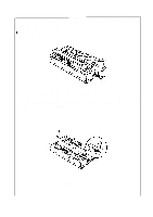
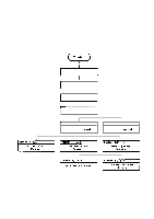
REV.-A 4.2 DISASSEMBLY AND ASSEMBLY Components of the FX-850\l 050 may be assembled simply by performing the disassembly operation in reverse sequence. Assembly procedures, therefore, have been omitted. The sequence of this disassembly in this section is grouped into three parts: (1) removal of the upper case, (2) removal of the circuit boards, and (3) disassembly of the printer mechanism. This sequence is shown in Figure 4-6. I Remove power cord, Interface cable, and paper. I Remove paper tension unit. Remove paper guide, paper rest, and printer cover. I Remove ribbon cartridge. I \ SectIon 4,2, 1 Upper Case Removai I 1 Sect Ion 4,2, 5,2 Printhead Removai Figure 4-6. Printer Disassembly Procedures 4-5
-
 1
1 -
2
-
3
-
4
-
5
-
6
-
7
-
8
-
9
-
10
-
11
-
12
-
13
-
14
-
15
-
16
-
17
-
18
-
19
-
20
-
21
-
22
-
23
-
24
-
25
-
26
-
27
-
28
-
29
-
30
-
31
-
32
-
33
-
34
-
35
-
36
-
37
-
38
-
39
-
40
-
41
-
42
-
43
-
44
-
45
-
46
-
47
-
48
-
49
-
50
-
51
-
52
-
53
-
54
-
55
-
56
-
57
-
58
-
59
-
60
-
61
-
62
-
63
-
64
-
65
-
66
-
67
-
68
-
69
-
70
-
71
-
72
-
73
-
74
-
75
-
76
-
77
-
78
-
79
-
80
-
81
-
82
-
83
-
84
-
85
-
86
-
87
-
88
-
89
-
90
-
91
-
92
-
93
-
94
-
95
-
96
-
97
-
98
-
99
-
100
-
101
-
102
-
103
-
104
-
105
-
106
-
107
-
108
-
109
-
110
-
111
-
112
-
 113
113 -
 114
114 -
 115
115 -
 116
116 -
 117
117 -
 118
118 -
 119
119 -
 120
120 -
 121
121 -
 122
122 -
 123
123 -
124
-
125
-
126
-
127
-
128
-
129
-
130
-
131
-
132
-
133
-
134
-
135
-
136
-
137
-
138
-
139
-
140
-
141
-
142
-
143
-
144
-
145
-
146
-
147
-
148
-
149
-
150
-
151
-
152
-
153
-
154
-
155
-
156
-
157
-
158
-
159
-
160
-
161
-
162
-
163
-
164
-
165
-
166
-
167
-
168
-
169
-
170
-
171
-
172
-
173
-
174
-
175
-
176
-
177
-
178
-
179
-
180
-
181
-
182
-
183
-
184
-
185
-
186
-
187
-
188
-
189
-
190
-
191
-
192
-
193
-
194
-
195
-
196
-
197
-
198
-
199
-
200
-
201
-
202
-
203
-
204
-
205
-
206
-
207
-
208
-
209
-
210
-
211
-
212
-
213
-
214
-
215
-
216
-
217
-
218
-
219
-
220
-
221
-
222
-
223
-
224
-
225
 |
 |

REV.-A
4.2
DISASSEMBLY AND ASSEMBLY
Components of the FX-850\l 050 may be assembled simply by performing the disassembly operation
in reverse sequence. Assembly procedures, therefore, have been omitted.
The sequence of this disassembly in this section is grouped into three parts: (1) removal of the upper
case, (2) removal of the circuit boards, and (3) disassembly of the printer mechanism. This sequence
is shown in Figure 4-6.
I
Remove power cord,
Interface cable, and paper.
I
Remove paper tension
unit.
Remove paper guide, paper
rest, and printer cover.
I
Remove ribbon cartridge.
I
\
1
SectIon
4,2, 1
Sect Ion 4,2, 5,2
Upper
Case
Removai
Printhead
Removai
I
Figure 4-6. Printer Disassembly Procedures
4-5