Epson LQ 1050 Technical Manual - Page 174
Unit Repair
 |
View all Epson LQ 1050 manuals
Add to My Manuals
Save this manual to your list of manuals |
Page 174 highlights
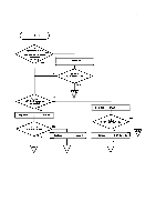
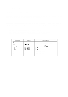
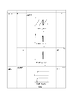
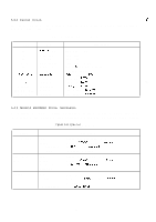
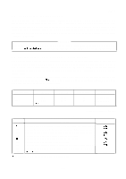
REV.-A 5.4 UNIT REPAIR Unit repair is comprised of three parts: ( 1 ) repair of the power supply circuit; (2) repair of the control circuit; (3) repair of the printer mechanism. This section describes (1) power supply circuit unit repair. If (2) control circuit, or (3) printer mechanism need repair, use the diagnostic tool introduced in Section 5.2. 5.4.1 Power Supply Circuit This section indicates possible causes and checkpoints for different of power supply circuit. The checkpoints include waveforms for normal operation. By referring to the checkpoints, determine the detective component and perform the proper repair. Table 5-6 has the following four columns: q Symptom: Check symptoms against those given in this column. q Cause: Check problems against the causes listed in this column. q Check Point: Use the instructions given in this column for troubleshooting. q Solution: Make repairs according to the instructions given in this column. Table 5-5. Power Supply Circuit Parts List Location IC 1A DB 1 Qlo, Q12 Q1 1 Q13 F2 F3 F4 Name NJM2355 DBF608 2SA1 450 2SC3748 2SC3746 - - - Description Pulse width modulation control Diode Bridge 100V, 6A 80V, 500mA, 600mW 60V, 10A 60V, 5A Fuse 250V, 3 15A Fuse 125V, 2A Fuse 125V, 2A 5-17
-
 1
1 -
2
-
3
-
4
-
5
-
6
-
7
-
8
-
9
-
10
-
11
-
12
-
13
-
14
-
15
-
16
-
17
-
18
-
19
-
20
-
21
-
22
-
23
-
24
-
25
-
26
-
27
-
28
-
29
-
30
-
31
-
32
-
33
-
34
-
35
-
36
-
37
-
38
-
39
-
40
-
41
-
42
-
43
-
44
-
45
-
46
-
47
-
48
-
49
-
50
-
51
-
52
-
53
-
54
-
55
-
56
-
57
-
58
-
59
-
60
-
61
-
62
-
63
-
64
-
65
-
66
-
67
-
68
-
69
-
70
-
71
-
72
-
73
-
74
-
75
-
76
-
77
-
78
-
79
-
80
-
81
-
82
-
83
-
84
-
85
-
86
-
87
-
88
-
89
-
90
-
91
-
92
-
93
-
94
-
95
-
96
-
97
-
98
-
99
-
100
-
101
-
102
-
103
-
104
-
105
-
106
-
107
-
108
-
109
-
110
-
111
-
112
-
113
-
114
-
115
-
116
-
117
-
118
-
119
-
120
-
121
-
122
-
123
-
124
-
125
-
126
-
127
-
128
-
129
-
130
-
131
-
132
-
133
-
134
-
135
-
136
-
137
-
138
-
139
-
140
-
141
-
142
-
143
-
144
-
145
-
146
-
147
-
148
-
149
-
150
-
151
-
152
-
153
-
154
-
155
-
156
-
157
-
158
-
159
-
160
-
161
-
162
-
163
-
164
-
165
-
166
-
167
-
168
-
 169
169 -
 170
170 -
 171
171 -
 172
172 -
 173
173 -
 174
174 -
 175
175 -
 176
176 -
 177
177 -
 178
178 -
 179
179 -
180
-
181
-
182
-
183
-
184
-
185
-
186
-
187
-
188
-
189
-
190
-
191
-
192
-
193
-
194
-
195
-
196
-
197
-
198
-
199
-
200
-
201
-
202
-
203
-
204
-
205
-
206
-
207
-
208
-
209
-
210
-
211
-
212
-
213
-
214
-
215
-
216
-
217
-
218
-
219
-
220
-
221
-
222
-
223
-
224
-
225
 |
 |
