Fluke 1550B FE 1550B Users Manual - Page 21
testing, confirm that the Meter does not indicate the presence of - megohmmeter battery
 |
View all Fluke 1550B manuals
Add to My Manuals
Save this manual to your list of manuals |
Page 21 highlights
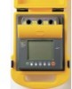
MegOhmMeter Making Measurements To perform an insulation test use the following procedure: 1. With the Meter turned on, set the available measurement options to meet your test requirements. These include: • Test Voltage - Set range: 250V to 5000 V (50 V/100 V steps) • Ramp Test - Toggle on or off • Time Limit - No limit or from 1 to 99 minutes 2. Connect the probes to the circuit you want to test. XW Warning To avoid possible electric shock or personal injury: before and after testing, confirm that the Meter does not indicate the presence of a hazardous voltage at the terminals. If the Meter beeps continuously and a hazardous voltage is shown on the display, disconnect test leads and remove power from the circuit under test. 3. Press the T button for 1 second to start the insulation test. The Meter beeps 3 times as the test begins, and the W icon flashes on the display indicating potentially hazardous voltages may be present on the test terminals. Digital Main Display V 5000V 2500V 000V 500V 250V 0M 00M G 0G M 00G 00k T 0 G Bar Graph ASW08F.EPS The digital display indicates the measured insulation resistance after the circuit has stabilized. The bar graph displays this value continuously (in real time) as a trend. Any of the following conditions will terminate an insulation test: • User stop (Pressing the T button). • Timer limit reached • Interference on the test circuit • Breakdown occurs with ramp test enabled • Battery depleted If breakdown occurs with ramp test enabled, press the e button before going to step 4. 15
-
 1
1 -
2
-
3
-
4
-
5
-
6
-
7
-
8
-
9
-
10
-
11
-
12
-
13
-
14
-
15
-
 16
16 -
 17
17 -
 18
18 -
 19
19 -
 20
20 -
 21
21 -
 22
22 -
 23
23 -
 24
24 -
 25
25 -
 26
26 -
27
-
28
-
29
-
30
-
31
-
32
-
33
-
34
-
35
-
36
 |
 |
