Fluke 8846A FE 8845A & 8846A Users Manual - Page 9
List of s - used
 |
View all Fluke 8846A manuals
Add to My Manuals
Save this manual to your list of manuals |
Page 9 highlights
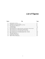
List of Figures Figure Title Page 2-1. Replacing the Line Fuse 2-5 2-2. Replacing the Current Input Fuses 2-6 2-3. Line Power Cords Types Available from Fluke 2-7 2-4. Bail Adjustment and Removal 2-8 3-1. TrendPlot Display 3-14 3-2. Histogram Display 3-14 4-1. Input Connections for Voltage, Resistance, and Frequency Measurements .......... 4-4 4-2. Input Connections for 4-Wire Resistance Measurements 4-8 4-3. Input Connections for 4-wire ohms using 2x4 wire leads 4-9 4-4. Input Connections for Current Measurements Below 120 mA 4-10 4-5. Input Connections for Current Measurements Above 120 mA 4-10 4-6. Measuring Capacitance 4-12 4-7. Temperature Measurements 4-13 4-8. Diode Testing Connections 4-15 4-9. TRIG I/O Pin-out Description 4-17 vii
-
 1
1 -
2
-
3
-
 4
4 -
 5
5 -
 6
6 -
 7
7 -
 8
8 -
 9
9 -
 10
10 -
 11
11 -
 12
12 -
 13
13 -
 14
14 -
15
-
16
-
17
-
18
-
19
-
20
-
21
-
22
-
23
-
24
-
25
-
26
-
27
-
28
-
29
-
30
-
31
-
32
-
33
-
34
-
35
-
36
-
37
-
38
-
39
-
40
-
41
-
42
-
43
-
44
-
45
-
46
-
47
-
48
-
49
-
50
-
51
-
52
-
53
-
54
-
55
-
56
-
57
-
58
-
59
-
60
-
61
-
62
-
63
-
64
-
65
-
66
-
67
-
68
-
69
-
70
-
71
-
72
-
73
-
74
-
75
-
76
-
77
-
78
-
79
-
80
-
81
-
82
-
83
-
84
-
85
-
86
-
87
-
88
-
89
-
90
-
91
-
92
-
93
 |
 |

vii
List of Figures
Figure
Title
Page
2-1.
Replacing the Line Fuse
.........................................................................................
2-5
2-2.
Replacing the Current Input Fuses
.........................................................................
2-6
2-3.
Line Power Cords Types Available from Fluke
.....................................................
2-7
2-4.
Bail Adjustment and Removal
...............................................................................
2-8
3-1.
TrendPlot Display
..................................................................................................
3-14
3-2.
Histogram Display
.................................................................................................
3-14
4-1.
Input Connections for Voltage, Resistance, and Frequency Measurements
..........
4-4
4-2.
Input Connections for 4-Wire Resistance Measurements
......................................
4-8
4-3.
Input Connections for 4-wire ohms using 2x4 wire leads
......................................
4-9
4-4.
Input Connections for Current Measurements Below 120 mA
..............................
4-10
4-5.
Input Connections for Current Measurements Above 120 mA
..............................
4-10
4-6.
Measuring Capacitance
..........................................................................................
4-12
4-7.
Temperature Measurements
...................................................................................
4-13
4-8.
Diode Testing Connections
....................................................................................
4-15
4-9.
TRIG I/O Pin-out Description
................................................................................
4-17