Foxconn H77M-S User manual - Page 24
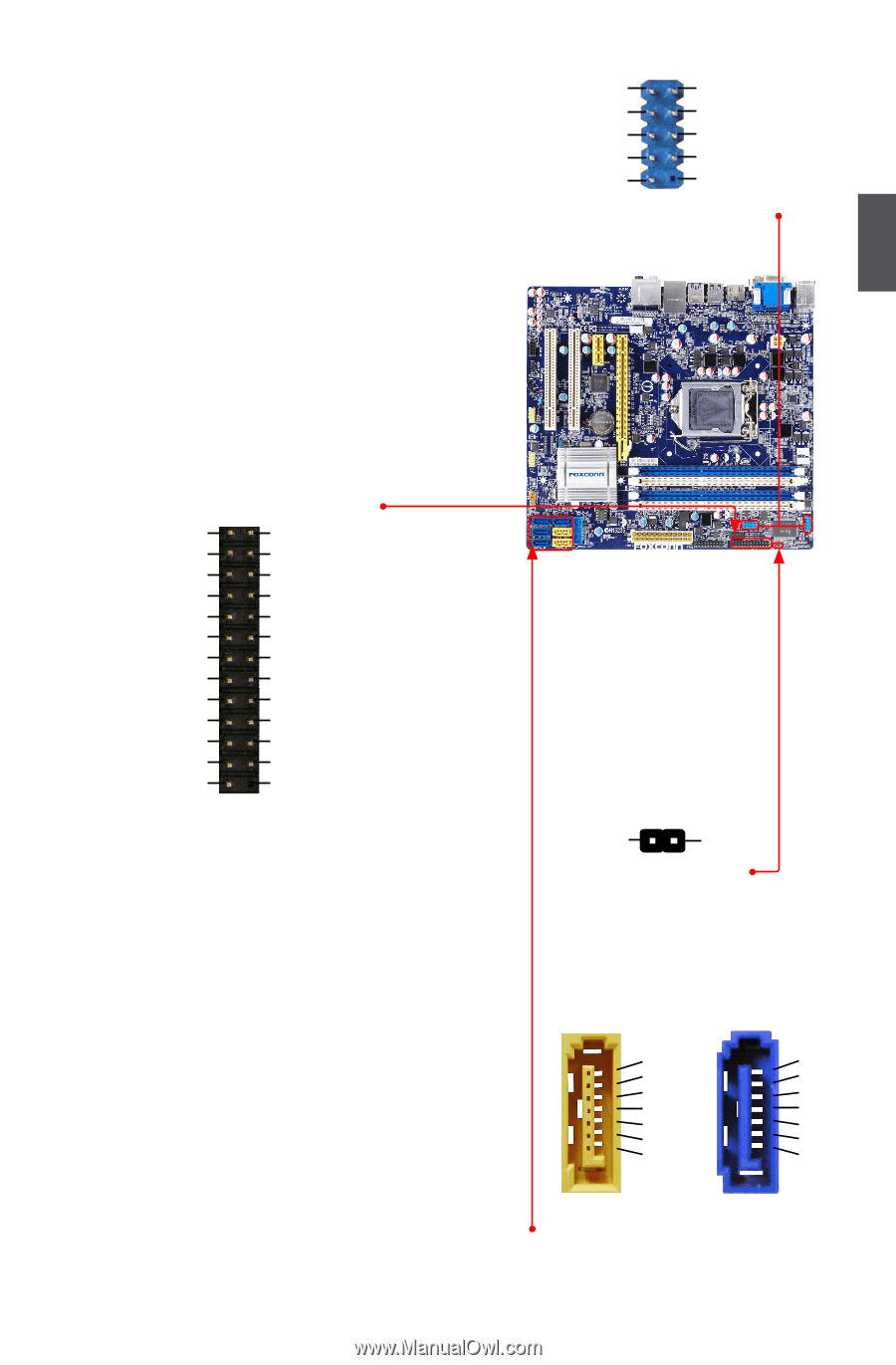
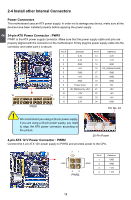
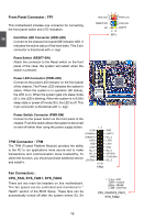
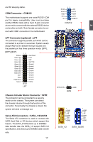
COM Connector : COM1/2, LPT Connector optional : LPT, Chassis Intruder Alarm Connector : INTR
 |
View all Foxconn H77M-S manuals
Add to My Manuals
Save this manual to your list of manuals |
Page 24 highlights
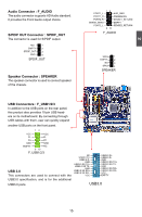
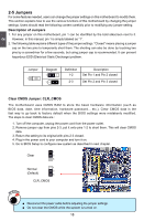
and S5 sleeping states. COM Connector : COM1/2 This motherboard supports one serial RS232 COM port for legacy compatibility. User must purchase another RS232 cable with a 9-pin D-sub connector at one end to connect with the external RS232 device and another end with 10-pin female connector to connect with COM1 connector in the motherboard. LPT Connector (optional) : LPT The connector supports parallel port which can be connected to a printer or a scanner. System usually assign IRQ7 as it's default interrupt request and the parallel port has three operation mode: [SPP], [EPP], [ECP]. Strobe Data it [0] Data it [1] Data it [2] Data it [3] Data it [4] Data it [5] Data it [6] Data it [7] ACK Busy Paper End Select 12 25 26 LPT Auto Feed Error INIT SLCT IN Ground Ground Ground Ground Ground Ground Ground Ground Empty Chassis Intruder Alarm Connector : INTR The connector can be connected to a security switch on the chassis. The system can detect the chassis intrusion through the function of this connector. If eventually the chassis is closed, the system will send a message out. Serial ATA Connectors : SATA_1/2/3/4/5/6 The Serial ATA connector is used to connect with SATA Hard Disk or CD devices which support this feature. The SATA_3/4/5/6 allows up to 300MB/s data transfer rate, the SATA_1/2 support SATA 3.0 specification, and allows up to 600MB/s data transfer rate. 17 17 12 RLSD SIN SOUT DTR GND DSR RTS CTS RI EMPTY 9 10 COM1/2 1 INTRUDERJ GND INTR 1 GND TX+ TX- GND RXRX+ GND 1 GND TX+ TX- GND RXRX+ GND SATA_1/2 SATA_3/4/5/6 2
-
 1
1 -
2
-
3
-
4
-
5
-
6
-
7
-
8
-
9
-
10
-
11
-
12
-
13
-
14
-
15
-
16
-
17
-
18
-
 19
19 -
 20
20 -
 21
21 -
 22
22 -
 23
23 -
 24
24 -
 25
25 -
 26
26 -
 27
27 -
 28
28 -
 29
29 -
30
-
31
-
32
-
33
-
34
-
35
-
36
-
37
-
38
-
39
-
40
-
41
-
42
-
43
-
44
-
45
-
46
-
47
-
48
-
49
-
50
-
51
-
52
-
53
-
54
-
55
-
56
-
57
-
58
-
59
-
60
-
61
-
62
-
63
-
64
-
65
-
66
-
67
-
68
-
69
-
70
-
71
-
72
-
73
-
74
-
75
-
76
-
77
-
78
-
79
-
80
-
81
-
82
-
83
-
84
-
85
-
86
-
87
-
88
-
89
-
90
-
91
-
92
-
93
-
94
-
95
-
96
-
97
-
98
-
99
-
100
-
101
-
102
-
103
-
104
-
105
-
106
 |
 |