Fujitsu MJA2500BH Maintenance Manual - Page 98
Cylinder High Field exp, Device/Head Field
 |
View all Fujitsu MJA2500BH manuals
Add to My Manuals
Save this manual to your list of manuals |
Page 98 highlights
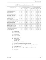
Interface (6) Cylinder High Field (exp) The contents of this field indicate high-order 8 bits of the disk-access start cylinder address. At the end of a command, the contents of this field are updated to the current cylinder number. The high-order 8 bits of the cylinder address are set to the Cylinder High Register. Under the LBA mode, this field indicates LBA bits 23 to 16. Under the LBA mode of the EXT system command, LBA bits 47 to 40 are set in the Cylinder High Field, and LBA bits 23 to 16 are set in the Cylinder High Field (exp). (7) Device/Head Field The contents of this field indicate the device and the head number. When executing INITIALIZE DEVICE PARAMETERS command, the contents of this field defines "the number of heads minus 1" (a maximum head No.). Bit 7 Bit 6 Bit 5 Bit 4 Bit 3 Bit 2 Bit 1 Bit 0 X L X X HS3 HS2 HS1 HS0 - Bit 7: Unused - Bit 6: L 0 for CHS mode and 1 for LBA mode. - Bit 5: Unused - Bit 4: Unused - Bit 3: HS3 CHS mode head address 3 (23). bit 27 for LBA mode. Unused under the LBA mode of the EXT command. - Bit 2: HS2 CHS mode head address 2 (22). bit 26 for LBA mode. Unused under the LBA mode of the EXT command. - Bit 1: HS1 CHS mode head address 1 (21). bit 25 for LBA mode. Unused under the LBA mode of the EXT command. - Bit 0: HS0 CHS mode head address 0 (20). bit 24 for LBA mode. Unused under the LBA mode of the EXT command. 5-24 C141-E293
-
 1
1 -
2
-
3
-
4
-
5
-
6
-
7
-
8
-
9
-
10
-
11
-
12
-
13
-
14
-
15
-
16
-
17
-
18
-
19
-
20
-
21
-
22
-
23
-
24
-
25
-
26
-
27
-
28
-
29
-
30
-
31
-
32
-
33
-
34
-
35
-
36
-
37
-
38
-
39
-
40
-
41
-
42
-
43
-
44
-
45
-
46
-
47
-
48
-
49
-
50
-
51
-
52
-
53
-
54
-
55
-
56
-
57
-
58
-
59
-
60
-
61
-
62
-
63
-
64
-
65
-
66
-
67
-
68
-
69
-
70
-
71
-
72
-
73
-
74
-
75
-
76
-
77
-
78
-
79
-
80
-
81
-
82
-
83
-
84
-
85
-
86
-
87
-
88
-
89
-
90
-
91
-
92
-
 93
93 -
 94
94 -
 95
95 -
 96
96 -
 97
97 -
 98
98 -
 99
99 -
 100
100 -
 101
101 -
 102
102 -
 103
103 -
104
-
105
-
106
-
107
-
108
-
109
-
110
-
111
-
112
-
113
-
114
-
115
-
116
-
117
-
118
-
119
-
120
-
121
-
122
-
123
-
124
-
125
-
126
-
127
-
128
-
129
-
130
-
131
-
132
-
133
-
134
-
135
-
136
-
137
-
138
-
139
-
140
-
141
-
142
-
143
-
144
-
145
-
146
-
147
-
148
-
149
-
150
-
151
-
152
-
153
-
154
-
155
-
156
-
157
-
158
-
159
-
160
-
161
-
162
-
163
-
164
-
165
-
166
-
167
-
168
-
169
-
170
-
171
-
172
-
173
-
174
-
175
-
176
-
177
-
178
-
179
-
180
-
181
-
182
-
183
-
184
-
185
-
186
-
187
-
188
-
189
-
190
-
191
-
192
-
193
-
194
-
195
-
196
-
197
-
198
-
199
-
200
-
201
-
202
-
203
-
204
-
205
-
206
-
207
-
208
-
209
-
210
-
211
-
212
-
213
-
214
-
215
-
216
-
217
-
218
-
219
-
220
-
221
-
222
-
223
-
224
-
225
-
226
-
227
-
228
-
229
-
230
-
231
-
232
-
233
-
234
-
235
-
236
-
237
-
238
-
239
-
240
-
241
-
242
-
243
-
244
-
245
-
246
-
247
-
248
-
249
-
250
-
251
-
252
-
253
-
254
-
255
-
256
-
257
-
258
-
259
-
260
-
261
-
262
-
263
-
264
-
265
-
266
-
267
-
268
-
269
-
270
-
271
-
272
-
273
-
274
-
275
-
276
-
277
-
278
-
279
-
280
-
281
-
282
-
283
-
284
-
285
-
286
-
287
-
288
-
289
-
290
-
291
-
292
-
293
-
294
-
295
-
296
-
297
-
298
-
299
-
300
-
301
-
302
-
303
-
304
-
305
-
306
-
307
-
308
-
309
-
310
-
311
-
312
-
313
-
314
-
315
-
316
-
317
-
318
-
319
-
320
 |
 |
