Fujitsu P50XHA10 User Manual - Page 8
PART NAMES AND FUNCTIONS Continued - 50
 |
View all Fujitsu P50XHA10 manuals
Add to My Manuals
Save this manual to your list of manuals |
Page 8 highlights
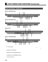
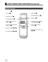
PART NAMES AND FUNCTIONS (Continued) DISPLAY SECTION - LOWER PART Bottom (P42VHA10 type) Bottom (P42HHA10 type) Bottom (50") Bottom (P42VHA20 type) 1 /I power switch When pressed while in the "OFF" state, the power indicator lamp lights and the display is placed in the "ON " state, and the power can be turned "ON" or "OFF" by the remote control or on the control panel of the display. When pressed while in the "ON " state, the power indicator lamp goes out and the display is placed in the "OFF" state where power is still partly supplied. 2 RS-232C terminal (RS-232C) This terminal is provided for you to control the display from the PC. Connect it to the RS-232C terminal on the PC. When connecting a cable, attach a ferrite core to the cable. (See P. E-13.) 3 RGB1 input terminal (RGB1 INPUT/DVI-D) Connect this terminal to the PC's display (digital RGB) output terminal. *The connection cable No.88741-8000 made by molex Inc. is recommanded. 4 RGB2 input terminal (RGB2 INPUT/mD-sub) Connect this terminal to the PC's display (analog RGB) output terminal or decoder (digital broadcast tuner, etc.) output terminal. 5 Power input terminal Connect this terminal to the power cable supplied with the display. When connecting a cable, attach a ferrite core to the cable. (See P. E-13.) E-8
-
 1
1 -
2
-
 3
3 -
 4
4 -
 5
5 -
 6
6 -
 7
7 -
 8
8 -
 9
9 -
 10
10 -
 11
11 -
 12
12 -
 13
13 -
14
-
15
-
16
-
17
-
18
-
19
-
20
-
21
-
22
-
23
-
24
-
25
-
26
-
27
-
28
-
29
-
30
-
31
-
32
-
33
-
34
-
35
-
36
-
37
-
38
-
39
-
40
-
41
-
42
-
43
-
44
-
45
 |
 |
