Fujitsu P50XHA10 User Manual - Page 9
Description of Input Terminals - speakers
 |
View all Fujitsu P50XHA10 manuals
Add to My Manuals
Save this manual to your list of manuals |
Page 9 highlights
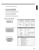
English 6 External speaker output terminal (EXT SP) Connect this terminal to the optionally available speaker. When connecting a cable, attach a ferrite core to the cable. (See P. E-13.) *See the speaker instruction manual for more information. 7 Audio1 input terminal (AUDIO1 INPUT) 8 Audio2 input terminal (AUDIO2 INPUT) 9 Audio3 input terminal (AUDIO3 INPUT) Connect this terminal to the sound output terminal of your VCR, etc. (See P.E-36 for the selection of audio input for video input.) 0 Component video input terminal (VIDEO3 INPUT) Connect this terminal to the component video output (color difference output) terminal of your HDTV unit or DVD player. A S-Video input terminal (VIDEO2 INPUT) Connect this terminal to the S-video output terminal of your VCR. B Video input terminal (VIDEO1 INPUT) Connect this terminal to the video output terminal of your VCR. C Component video input terminal (VIDEO4 INPUT) Connect this terminal to the component video output (color difference output) terminal of your HDTV unit or DVD player. Description of Input Terminals DVI-D terminal (RGB1 INPUT/DVI-D) RGB2 input terminal (RGB2 INPUT/mD-sub) Pin No. 1 2 3 4 5 6 7 8 Input signal Red Green Blue - Ground Ground Ground Ground Pin No. 9 10 11 12 13 14 15 Frame Input signal - Ground - - Horizontal synchronization Vertical synchronization - Ground RS-232C terminal (RS-232C) Pin No. 1 2 3 4 5 6 7 8 9 Signal DCD (Data Carrier Detect) RD (Received Data) TD (Transmit Data) DTR (Data Terminal ready) GND (Ground) DSR (Data Set Ready) RTS (Request To send) CTS (Clear To Send) RI (Ring Indication) E-9
-
 1
1 -
2
-
3
-
 4
4 -
 5
5 -
 6
6 -
 7
7 -
 8
8 -
 9
9 -
 10
10 -
 11
11 -
 12
12 -
 13
13 -
 14
14 -
15
-
16
-
17
-
18
-
19
-
20
-
21
-
22
-
23
-
24
-
25
-
26
-
27
-
28
-
29
-
30
-
31
-
32
-
33
-
34
-
35
-
36
-
37
-
38
-
39
-
40
-
41
-
42
-
43
-
44
-
45
 |
 |
