Garmin Edge 810 Owner's Manual - Page 10
Installing the GSC 10, Training with Power Meters - owners manual
 |
View all Garmin Edge 810 manuals
Add to My Manuals
Save this manual to your list of manuals |
Page 10 highlights
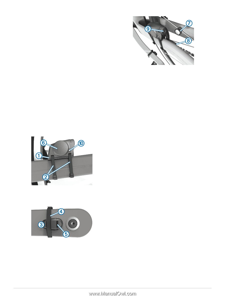
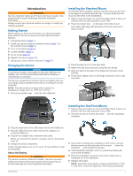
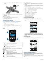
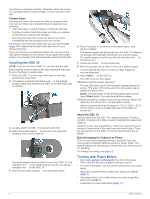
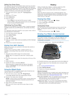
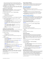
according to increasing intensity. Generally, heart rate zones are calculated based on percentages of your maximum heart rate. Fitness Goals Knowing your heart rate zones can help you measure and improve your fitness by understanding and applying these principles. • Your heart rate is a good measure of exercise intensity. • Training in certain heart rate zones can help you improve cardiovascular capacity and strength. • Knowing your heart rate zones can prevent you from overtraining and can decrease your risk of injury. If you know your maximum heart rate, you can use the table (page 16) to determine the best heart rate zone for your fitness objectives. If you do not know your maximum heart rate, use one of the calculators available on the Internet. Some gyms and health centers can provide a test that measures maximum heart rate. Installing the GSC 10 NOTE: If you do not have a GSC 10, you can skip this task. Both magnets must be aligned with their respective indication lines for the Edge to receive data. 1 Place the GSC 10 on the rear chain stay (on the side opposite the drive train). 2 If necessary, place the flat rubber pad À or the triangle- shaped rubber pad between the GSC 10 and the chain stay for stability. 3 Loosely attach the GSC 10 using two cable ties Á. 4 Attach the pedal magnet  to the crank arm using the adhesive mount and a cable tie Ã. The pedal magnet must be within 5 mm of the GSC 10. The indication line Ä on the pedal magnet must line up with the indication line Å on the GSC 10. 5 Unscrew the spoke magnet Æ from the plastic piece. 6 Place the spoke in the groove of the plastic piece, and tighten it slightly. The spoke magnet can face away from the GSC 10 if there is not enough room between the sensor arm and the spoke. The spoke magnet must line up with the indication line Ç on the sensor arm. 7 Loosen the screw È on the sensor arm. 8 Move the sensor arm to within 5 mm of the spoke magnet. You can also tilt the GSC 10 closer to either magnet to improve alignment. 9 Select Reset É on the GSC 10. The LED turns red, then green. 10 Pedal to test the sensor alignment. The red LED blinks each time the pedal magnet passes the sensor. The green LED blinks each time the spoke magnet passes the sensor arm. NOTE: The LED blinks for the first 60 passes after a reset. Select Reset again if you require additional passes. 11When everything is aligned and working correctly, tighten the cable ties, the sensor arm, and the spoke magnet. Garmin recommends that the torque is 1. 9 to 2. 4 lbf-in. (0. 21 to 0. 27 N-m) to ensure a water tight seal on the GSC 10 sensor arm. About the GSC 10 Cadence data from the GSC 10 is always recorded. If there is no GSC 10 paired, GPS data is used to calculate the speed and distance. Cadence is your rate of pedaling or "spinning" measured by the number of revolutions of the crank arm per minute (rpm). There are two sensors on the GSC 10: one for cadence and one for speed. Data Averaging for Cadence or Power The non-zero data-averaging setting is available if you are training with an optional cadence sensor or power meter. The default setting is to exclude zero values that occur when you are not pedaling. To change this setting, see page 12. Training with Power Meters • Go to www.garmin.com/ intosports for a list of third-party ANT + sensors that are compatible with your device. • For more information, see the owner's manual for your power meter. • Adjust your power zones to match your goals and abilities (page 7). • Use range alerts to be notified when you reach a specified power zone (page 3). • Customize the power data fields (page 11). 6 ANT+ Sensors
-
 1
1 -
2
-
3
-
4
-
 5
5 -
 6
6 -
 7
7 -
 8
8 -
 9
9 -
 10
10 -
 11
11 -
 12
12 -
 13
13 -
 14
14 -
 15
15 -
16
-
17
-
18
-
19
-
20
-
21
-
22
 |
 |