Garmin GAD 42 Maintenance Manual - Page 9
DC Analog-to-Digital Converter, XYZ Synchro Output Processing, Digital-to-Analog Converter, Output - roll steering
 |
View all Garmin GAD 42 manuals
Add to My Manuals
Save this manual to your list of manuals |
Page 9 highlights
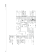
7.8 DC Analog-to-Digital Converter The DC A/D converter on the CPU PC Board is a 10-channel, 8 bit, serial interface converter. It is used for all DC voltage monitoring in the GAD 42. All 26 Vac reference inputs are read by this device for validity checking. In addition, this device reads all internal DC voltages for the same purpose. Resistor scaling networks scale the sampled voltages to the 0 to 5 V range required by the A/D converter. The negative voltages are summed with positive voltages to bring them into the required voltage range. Diode clamps protect the A/D inputs from negative or over-voltage where required. A ceramic capacitor filter reduces noise on each input. 7.9 XYZ Synchro Output Processing Because all XYZ synchro outputs (shown in the upper right corner of the block diagram) are processed by identical circuitry, only the SELECTED CRS DRIVE X/COS and SELECTED CRS DRIVE Y/SIN outputs will be discussed here. All Z synchro outputs are grounded in the GAD 42. 7.10 Digital-to-Analog Converter All synchro X and Y outputs originate at D/A converters on the CPU PC board. The D/A converters simply provide an amplitude-scaled version of the signal input to the VREF input. As previously described, the VREF input is a scaled version of the 26 Vac reference input associated with that signal. The amplitude is scaled from -1 (inverted) through 0 to +1 (non-inverted). Full-scale amplitude at the D/A outputs is 4.7 Vac. The relative amplitude of the X or COS to the Y or SIN determines the angle information to be transmitted to an indicator. The D/A converter outputs are then sent to the Analog PC board where they are amplified by the output amp. 7.11 Output Amplifiers The output amps use a unity-gain buffer amp, a high-voltage op-amp, and inverting push-pull Darlington driver transistors all within a common feedback loop. The overall amp gain is set by the ratio of two resistors. Control loop stability is maintained by feedback caps across the opamp, across the push-pull drivers, and by an output capacitor. The push-pull drivers are protected from over-voltage transients by a transient protection zener. The SELECTED CRS DRIVE X/COS and SELECTED CRS DRIVE Y/SIN outputs have an additional circuit element not present on other synchro outputs. This element is the output relay. It is present to turn off SELECTED COURSE DRIVE from indicators requiring it to not be present during certain operating conditions. The ROLL STEERING output amp is the same topology as described above, but uses lower power and lower gain push-pull output amps. This is possible due to higher impedance loads being driven by this output. GAD 42 MAINTENANCE MANUAL P/N 190-00159-01 Page 8 Rev. A
-
 1
1 -
2
-
3
-
 4
4 -
 5
5 -
 6
6 -
 7
7 -
 8
8 -
 9
9 -
 10
10 -
 11
11 -
 12
12 -
 13
13 -
 14
14
 |
 |