Garmin GMA 240 Installation Manual - Page 19
Installation Procedure
 |
View all Garmin GMA 240 manuals
Add to My Manuals
Save this manual to your list of manuals |
Page 19 highlights
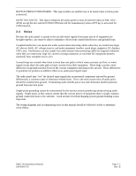
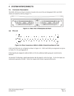
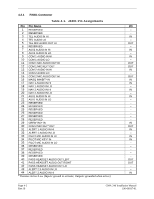
3 INSTALLATION PROCEDURE 3.1 Unpacking Unit Carefully unpack the equipment and make a visual inspection of the unit for evidence of damage incurred during shipment. If the unit is damaged, notify the carrier and file a claim. To justify a claim, save the original shipping container and all packing materials. Do not return the unit to Garmin until the carrier has authorized the claim. Retain the original shipping containers for storage. If the original containers are not available, a separate cardboard container should be prepared that is large enough to accommodate sufficient packing material to prevent movement. 3.2 Electrical Connections All electrical connections to the GMA 240 are made through two 44-pin D-subminiature connectors (see Figure 3-1). Section 4 defines the electrical characteristics of all input and output signals. Required connector and associated hardware are supplied in the connector kit (P/N 011-00652-00). See Appendix B for interconnect wiring diagrams. Check wiring connections for errors before inserting the GMA 240 into the rack. Incorrect wiring could cause internal component damage. Table 3-1. Pin Contact Part Numbers Manufacturer 22-28 AWG Garmin P/N 336-00021-00 Military P/N M39029/58-360 AMP 204370-2 Positronic MC8522D ITT Cannon 030-2042-000 Table 3-2. Recommended Crimp Tools Manufacturer Hand Crimping Tool High Density 20-28 AWG Positioner Insertion/ Extraction Tool Military P/N Positronic ITT Cannon AMP Daniels Astro M22520/2-01 9507 995-0001-584 601966-1 AFM8 615717 M22520/2-09 9502-3 995-0001-739 601966-6 K42 615725 M81969/1-04 M81969/1-04 N/A 91067-1 M81969/1-04 M81969/1-04 NOTE 1. Non-Garmin part numbers shown are not maintained by Garmin and consequently are subject to change without notice. 2. Extracting the #16, #18 and #20 contact requires that the expanded wire barrel be cut off from the contact. It may also be necessary to push the pin out from the face of the connector when using an extractor due to the absence of the wire. A new contact must be used when reassembling the connector. 3. For applications using 16 AWG wire, contact Garmin for information regarding connector crimp positioner tooling. GMA 240 Installation Manual 190-00917-01 Page 3-1 Rev. B
-
 1
1 -
2
-
3
-
4
-
5
-
6
-
7
-
8
-
9
-
10
-
11
-
12
-
13
-
 14
14 -
 15
15 -
 16
16 -
 17
17 -
 18
18 -
 19
19 -
 20
20 -
 21
21 -
 22
22 -
 23
23 -
 24
24 -
25
-
26
-
27
-
28
-
29
-
30
-
31
-
32
-
33
-
34
-
35
-
36
-
37
-
38
 |
 |
