Garmin GMA 240 Installation Manual - Page 5

List Of Illustrations, List Of Tables - audio panel

Page 5 highlights

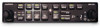
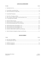
LIST OF ILLUSTRATIONS FIGURE PAGE 1-1 GMA 240 Unit View ...1-1 2-1 Access Hole Location (Top View) ...2-4 2-2 GMA 340 Unit Rack (115-00262-00 2-6 3-1 Audio Shield Termination ...3-2 4-1 Rear View of Backplate and Rack ...4-1 4-2 Rear Connectors J2401 & J2402, Viewed from Back of Unit 4-1 4-3 2.5 mm Plug Used with P2403 ...4-4 A-1 GMA 240 Outline Drawing ...A-1 A-2 GMA 240 Connector/Rack Assembly Drawing A-3 A-3 GMA 240 Recommended Panel Cutout Dimensions A-5 B-1 GMA 240 Interconnect Drawing (page 1 of 3 B-1 B-1 GMA 240 Interconnect Drawing (page 2 of 3 B-3 B-1 GMA 240 Interconnect Drawing (page 3 of 3 B-5 B-2 GMA 240, J2401 & J2402 Connector Layout Drawing B-7 C-1 GMA 240 Internal Configuration Jumper Layout Drawing C-1 LIST OF TABLES TABLE PAGE 3-1 Pin Contact Part Numbers...3-1 3-2 Recommended Crimp Tools ...3-1 4-1 J2401 Pin Assignments ...4-2 4-2 J2402 Pin Assignments ...4-3 GMA 240 Installation Manual 190-00917-01 Page iii Revision B

  • 1
  • 2
  • 3
  • 4
  • 5
  • 6
  • 7
  • 8
  • 9
  • 10
  • 11
  • 12
  • 13
  • 14
  • 15
  • 16
  • 17
  • 18
  • 19
  • 20
  • 21
  • 22
  • 23
  • 24
  • 25
  • 26
  • 27
  • 28
  • 29
  • 30
  • 31
  • 32
  • 33
  • 34
  • 35
  • 36
  • 37
  • 38

GMA 240 Installation Manual
Page iii
190-00917-01
Revision B
LIST OF ILLUSTRATIONS
FIGURE
PAGE
1-1 GMA 240 Unit View
.........................................................................................................................
1-1
2-1 Access Hole Location (Top View)
....................................................................................................
2-4
2-2 GMA 340 Unit Rack (115-00262-00)
...............................................................................................
2-6
3-1 Audio Shield Termination
.................................................................................................................
3-2
4-1
Rear View of Backplate and Rack
.....................................................................................................
4-1
4-2
Rear Connectors J2401 & J2402, Viewed from Back of Unit
...........................................................
4-1
4-3
2.5 mm Plug Used with P2403
..........................................................................................................
4-4
A-1 GMA 240 Outline Drawing
..............................................................................................................
A-1
A-2 GMA 240 Connector/Rack Assembly Drawing
...............................................................................
A-3
A-3 GMA 240 Recommended Panel Cutout Dimensions
.......................................................................
A-5
B-1 GMA 240 Interconnect Drawing (page 1 of 3)
.................................................................................
B-1
B-1 GMA 240 Interconnect Drawing (page 2 of 3)
.................................................................................
B-3
B-1 GMA 240 Interconnect Drawing (page 3 of 3)
.................................................................................
B-5
B-2 GMA 240, J2401 & J2402 Connector Layout Drawing
...................................................................
B-7
C-1 GMA 240 Internal Configuration Jumper Layout Drawing
.............................................................
C-1
LIST OF TABLES
TABLE
PAGE
3-1 Pin Contact Part Numbers
..................................................................................................................
3-1
3-2 Recommended Crimp Tools
..............................................................................................................
3-1
4-1 J2401 Pin Assignments
......................................................................................................................
4-2
4-2 J2402 Pin Assignments
......................................................................................................................
4-3