Garmin GMA 240 Installation Manual - Page 26
Aircraft Power and Lighting
 |
View all Garmin GMA 240 manuals
Add to My Manuals
Save this manual to your list of manuals |
Page 26 highlights
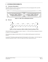
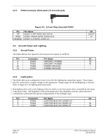
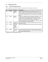
4.2.3 P2403 Connector (front panel 2.5 mm mini-jack) Figure 4-3. 2.5 mm Plug Used with P2403 Pin TIP RING SLEEVE Pin Name MUSIC 1 LEFT IN/TEL MIC OUT HI MUSIC 1 RIGHT IN/TEL AUDIO IN HI MUSIC 1 LO IN/TEL AUDIO LO 4.3 Aircraft Power and Lighting 4.3.1 Aircraft Power The GMA 240 has four inputs for aircraft power bus inputs of 14/28Vdc. Pin Connector Pin Name 8 P2402 AIRCRAFT POWER 9 P2402 AIRCRAFT POWER 10 P2402 POWER GROUND 11 P2402 POWER GROUND I/O IN/OUT IN -- I/O IN IN --- 4.3.2 Lighting Bus The GMA 240 can be configured to track a 14 or 28 Vdc lighting bus using these inputs. These inputs must be connected to a supply voltage (in the appropriate voltage range) for the backlighting to function. Refer to Figure B-1 for lighting interconnections. Backlighting refers only to the lighting of the text labels on the front panel and is controlled by the inputs in the below table. The brightness of the LED annunciators that illuminate each key when selected is controlled by a photocell that operates independently of the backlight input. Pin Connector Pin Name I/O 5 P2402 LIGHTING BUS 14V LO/28V LO -- 6 P2402 LIGHTING BUS 14V HI/28V LO IN 7 P2402 LIGHTING BUS 14V HI/28V HI IN Page 4-4 Rev. B GMA 240 Installation Manual 190-00917-01
-
 1
1 -
2
-
3
-
4
-
5
-
6
-
7
-
8
-
9
-
10
-
11
-
12
-
13
-
14
-
15
-
16
-
17
-
18
-
19
-
20
-
 21
21 -
 22
22 -
 23
23 -
 24
24 -
 25
25 -
 26
26 -
 27
27 -
 28
28 -
 29
29 -
 30
30 -
 31
31 -
32
-
33
-
34
-
35
-
36
-
37
-
38
 |
 |
