Garmin GMA 240 Installation Manual - Page 30
Tel Audio I/O, Connector, Pin Name, Description, Headset Outputs, COM Swap - gma 340 installation manual
 |
View all Garmin GMA 240 manuals
Add to My Manuals
Save this manual to your list of manuals |
Page 30 highlights
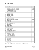
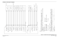
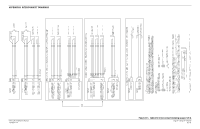
4.5.8 Pin 3 4 5 Tel Audio I/O Connector P2401 P2401 P2401 Pin Name TEL AUDIO IN HI TEL AUDIO LO TEL MIC AUDIO OUT HI Description Telephone Audio Input Ground Reference for Telephone TEL MIC Audio Output I/O IN -OUT 4.5.9 Headset Outputs Pin Connector Pin Name 16 P2402 PILOT HEADSET AUDIO OUT LEFT 31 P2402 PILOT HEADSET AUDIO OUT RIGHT 1 P2402 PILOT HEADSET AUDIO OUT LO 3 P2402 COPILOT HEADSET AUDIO OUT LEFT 4 P2402 COPILOT HEADSET AUDIO OUT RIGHT 2 P2402 COPILOT HEADSET AUDIO OUT LO 40 P2401 PASS HEADSET AUDIO OUT LEFT 41 P2401 PASS HEADSET AUDIO OUT RIGHT 42 P2401 PASS HEADSET AUDIO OUT LO Description Pilot Headset Audio Output Copilot Headset Audio Output Passenger Headset Audio Output I/O OUT OUT -OUT OUT -OUT OUT -- NOTE Copilot and Passenger headset outputs are internally the same connection. Separate Passenger headset output pins are provided for wiring convenience and GMA 340 pin compatibility. NOTE For CREW ISO configuration, the copilot's headphone jack should be wired in parallel with the pilot jack to the Pilot headset output pins. Passengers may be connected to either the copilot or passenger pins. 4.5.10 Pin 20 COM Swap Connector Pin Name P2402 COM SWAP* IN 21 P2402 COM SWAP RETURN Description I/O Ground Through a Momentary PB IN Switch to Swap Active COM (COM 1 or COM 2) Return Path for PB Switch -- Page 4-8 Rev. B GMA 240 Installation Manual 190-00917-01
-
 1
1 -
2
-
3
-
4
-
5
-
6
-
7
-
8
-
9
-
10
-
11
-
12
-
13
-
14
-
15
-
16
-
17
-
18
-
19
-
20
-
21
-
22
-
23
-
24
-
 25
25 -
 26
26 -
 27
27 -
 28
28 -
 29
29 -
 30
30 -
 31
31 -
 32
32 -
 33
33 -
 34
34 -
 35
35 -
36
-
37
-
38
 |
 |
