Page ii
GMA 240 Installation Manual
Revision B
190-00917-01
TABLE OF CONTENTS
PARAGRAPH
PAGE
1
GENERAL DESCRIPTION
..............................................................................................................
1-1
1.1 Introduction
........................................................................................................................................
1-1
1.2 Equipment Description
......................................................................................................................
1-1
1.3 Technical Specifications
....................................................................................................................
1-2
1.4 Reference Documents
........................................................................................................................
1-4
1.5 Limited Warranty
...............................................................................................................................
1-5
2
INSTALLATION OVERVIEW
........................................................................................................
2-1
2.1 Introduction
........................................................................................................................................
2-1
2.2 Installation Materials
.........................................................................................................................
2-1
2.3
GMA 240 Wiring, Configuration, and Adjustment Options
.............................................................
2-1
2.4 Noise
..................................................................................................................................................
2-5
2.5 GMA 240 Mounting
..........................................................................................................................
2-6
3
INSTALLATION PROCEDURE
......................................................................................................
3-1
3.1 Unpacking Unit
..................................................................................................................................
3-1
3.2 Electrical Connections
.......................................................................................................................
3-1
3.3 Audio Shield Termination
.................................................................................................................
3-2
3.4 GMA 240 Installation
........................................................................................................................
3-2
3.5 Post Installation Checkout
.................................................................................................................
3-3
3.6 Configuration Adjustments
................................................................................................................
3-4
3.7 Continued Airworthiness
...................................................................................................................
3-4
4
SYSTEM INTERCONNECTS
..........................................................................................................
4-1
4.1 Connector Description
.......................................................................................................................
4-1
4.2 Pin List
...............................................................................................................................................
4-1
4.3
Aircraft Power and Lighting
..............................................................................................................
4-4
4.4 Configuration Pins
.............................................................................................................................
4-5
4.5
Audio Inputs/Outputs and Mic Keys
.................................................................................................
4-6
APPENDIX A
OUTLINE AND INSTALLATION DRAWINGS
..........................................................
A-1
APPENDIX B
INTERCONNECT DRAWINGS
....................................................................................
B-1
APPENDIX C
CONFIGURATION JUMPER DRAWINGS
..................................................................
C-1
 1
1 2
2 3
3 4
4 5
5 6
6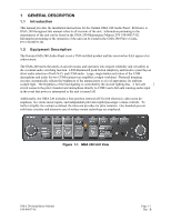 7
7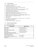 8
8 9
9 10
10