Garmin GMA 240 Installation Manual - Page 23
System Interconnects
 |
View all Garmin GMA 240 manuals
Add to My Manuals
Save this manual to your list of manuals |
Page 23 highlights
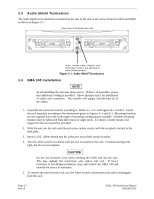
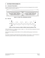
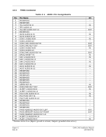
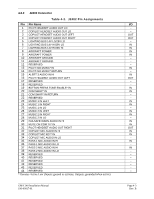
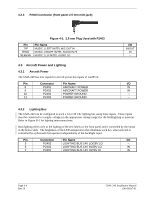
4 SYSTEM INTERCONNECTS 4.1 Connector Description The GMA 240 has two 44-pin connectors located at the rear of the unit designated J2401 and J2402 which are oriented as shown in Figure 4-1. 4.2 Pin List J2402 J2401 Figure 4-1. Rear View of Backplate and Rack Figure 4-2. Rear Connectors J2401 & J2402, Viewed from Back of Unit J2401 and J2402 pins are configured as shown in Figure 4-2. J2401 and J2402 pin assignments are given in Tables 4-1, 4-2, and Appendix B. Following the pin assignment tables (Tables 4-1 & 4-2), additional tables group pin connections by function. An asterisk (*) following a signal name denotes that the signal is active low logic. Active low inputs are connected to ground to activate. Active low outputs sink current to ground when active. GMA 240 Installation Manual 190-00917-01 Page 4-1 Rev. B
-
 1
1 -
2
-
3
-
4
-
5
-
6
-
7
-
8
-
9
-
10
-
11
-
12
-
13
-
14
-
15
-
16
-
17
-
 18
18 -
 19
19 -
 20
20 -
 21
21 -
 22
22 -
 23
23 -
 24
24 -
 25
25 -
 26
26 -
 27
27 -
 28
28 -
29
-
30
-
31
-
32
-
33
-
34
-
35
-
36
-
37
-
38
 |
 |
