Garmin GNS 430W Quick Reference Guide - Page 19
large right - specifications
 |
View all Garmin GNS 430W manuals
Add to My Manuals
Save this manual to your list of manuals |
Page 19 highlights
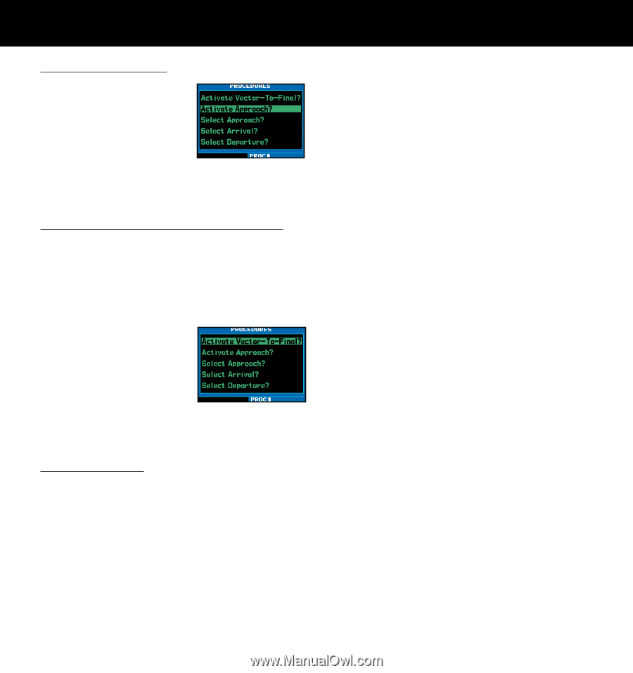
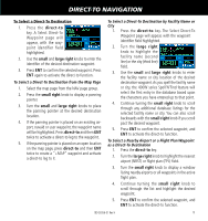
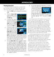
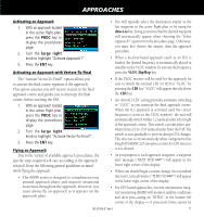
APPROACHES Activating an Approach 1. With an approach loaded in the active flight plan, press the PROC key to display the procedures page. 2. Turn the large right knob to highlight "Activate Approach?". 3. Press the ENT key. Activating an Approach with Vectors-To-Final • You will typically select the destination airport as the last waypoint in the active flight plan or by using the direct-to key. Doing so ensures that the desired waypoint will automatically appear when choosing the "Select Approach?" option from the procedures page. Otherwise, you must first choose the airport, then the approach procedure. • When a localizer-based approach (such as an ILS) is loaded, the desired frequency is automatically placed in standby on the VLOC window. To activate the frequency, press the VLOC flip/flop key. The "Activate Vector-To-Final?" option allows you to activate the final course segment of the approach. This option assumes you will receive vectors to the final approach course and guides you to intercept the final course, before reaching the FAF. 1. With an approach loaded in the active flight plan, press the PROC key to display the procedures page. 2. Turn the large right knob to highlight "Activate Vector-To-Final?". 3. Press the ENT key. Flying an Approach Due to the variety of available approach procedures, the specific steps required will vary according to the approach selected. Keep the following general guidelines in mind while flying the approach: • The 400W series is designed to complement your printed approach plates and improve situational awareness throughout the approach. However, you must always fly an approach as it appears on the approach plate. • If the VLOC receiver will be used for the approach, be sure to switch the external CDI (or HSI) to "VLOC" by pressing the CDI key. "VLOC" will appear directly above the CDI key. • An "Auto ILS CDI" setting provides automatic switching to "VLOC" as you intercept the final approach course. When the ILS approach is activated (and the correct frequency is active in the VLOC window), the unit will automatically switch within 1.2 nautical miles left or right of the approach course. This switch can take place anywhere from 2.0 to 15.0 nautical miles from the FAF. The switch occurs gradually to prevent abrupt CDI changes. This does not occur automatically when configured for the King KAP140/KFC225 autopilots as Auto ILS CDI Selection is not allowed. • As you progress to each approach waypoint, a waypoint alert message ("NEXT DTK ###°") will appear in the lower right corner of the display. • When you should begin a course change (via a standard rate turn), turn advisories ("TURN TO ###°") will appear in the lower right corner of the display. • For GPS-based approaches, receiver autonomous integrity monitoring (RAIM) will monitor satellite conditions and alert you-using an "INTEG" at the bottom left corner of the display - if protection limits cannot be 190-00356-01 Rev H 17
-
 1
1 -
2
-
3
-
4
-
5
-
6
-
7
-
8
-
9
-
10
-
11
-
12
-
13
-
 14
14 -
 15
15 -
 16
16 -
 17
17 -
 18
18 -
 19
19 -
 20
20 -
 21
21 -
 22
22 -
 23
23 -
 24
24
 |
 |