Gateway LT3114u Service Guide - Page 55
WLAN Board, Remove the single screw securing the WLAN Board in place.
 |
UPC - 884483848164
View all Gateway LT3114u manuals
Add to My Manuals
Save this manual to your list of manuals |
Page 55 highlights
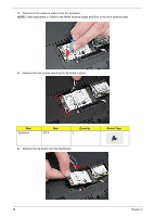
4. Disconnect the Antenna cables from the WLAN Board. NOTE: Cable placement is White to the MAIN terminal (right) and Black to the AUX terminal (left). 5. Remove the single screw securing the WLAN Board in place. Step WLAN Board Size M2*3 Quantity 1 Screw Type Chapter 3 45
-
 1
1 -
2
-
3
-
4
-
5
-
6
-
7
-
8
-
9
-
10
-
11
-
12
-
13
-
14
-
15
-
16
-
17
-
18
-
19
-
20
-
21
-
22
-
23
-
24
-
25
-
26
-
27
-
28
-
29
-
30
-
31
-
32
-
33
-
34
-
35
-
36
-
37
-
38
-
39
-
40
-
41
-
42
-
43
-
44
-
45
-
46
-
47
-
48
-
49
-
 50
50 -
 51
51 -
 52
52 -
 53
53 -
 54
54 -
 55
55 -
 56
56 -
 57
57 -
 58
58 -
 59
59 -
 60
60 -
61
-
62
-
63
-
64
-
65
-
66
-
67
-
68
-
69
-
70
-
71
-
72
-
73
-
74
-
75
-
76
-
77
-
78
-
79
-
80
-
81
-
82
-
83
-
84
-
85
-
86
-
87
-
88
-
89
-
90
-
91
-
92
-
93
-
94
-
95
-
96
-
97
-
98
-
99
-
100
-
101
-
102
-
103
-
104
-
105
-
106
-
107
-
108
-
109
-
110
-
111
-
112
-
113
-
114
-
115
-
116
-
117
-
118
-
119
-
120
-
121
-
122
-
123
-
124
-
125
-
126
-
127
-
128
-
129
-
130
-
131
-
132
-
133
-
134
-
135
-
136
-
137
-
138
-
139
-
140
-
141
-
142
-
143
-
144
-
145
-
146
-
147
-
148
-
149
-
150
-
151
-
152
-
153
-
154
-
155
-
156
-
157
-
158
-
159
-
160
-
161
-
162
-
163
-
164
-
165
-
166
-
167
-
168
-
169
-
170
-
171
-
172
-
173
-
174
-
175
-
176
-
177
-
178
-
179
-
180
 |
 |

Chapter 3
45
4.
Disconnect the Antenna cables from the WLAN Board.
NOTE:
Cable placement is White to the MAIN terminal (right) and Black to the AUX terminal (left).
5.
Remove the single screw securing the WLAN Board in place.
Step
Size
Quantity
Screw Type
WLAN Board
M2*3
1