GE JVM1790SK Service Manual - Page 23
Interlock System
 |
UPC - 084691123453
View all GE JVM1790SK manuals
Add to My Manuals
Save this manual to your list of manuals |
Page 23 highlights
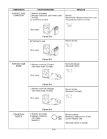
INTERLOCK SYSTEM INTERLOCK MECHANISM The door lock mechanism is a device which has been specially designed to eliminate completely microwave activity when the door is opened during cooking and thus to prevent the danger resulting from the microwave leakage. ADJUSTMENT PROCEDURES To avoid possible exposure to microwave energy leakage, adjust the door latches and interlock switches, using the following procedure. The Interlock Monitor and Secondary Interlock Switch act as the final safety switch protecting the user from microwave energy. The terminals between "COM" and "NC" of the Interlock Monitor must close when the door is opened. After adjusting the Interlock Monitor Switch, make sure that it is correctly connected. Mounting of the primary/monitor/secondary switches to the latch board. CHECK THE DOOR LATCH AND SWITCH CLOSING. NOTE: The outer cover of the microwave oven is removed. (1) Set the microwave oven on its side so that you can see the latch board and the switches, as shown in Figure 24-a. (2) Close the door tightly and check gaps A and B to be sure they are no more than 1/64" (0.5 mm). See Figure 23 for close-up view of gaps A and B (door latches). If all gaps are less than 1/64" (0.5 mm), adjustment of the latch board may not be necessary. Go to Steps 5 and 6 to check the sequence of the switches. Latch Board Primary Interlock Switch NOTE: To correct sequence of the Primary Interlock Switch, Secondary Interlock Switch and the Interlock Monitor Switch is very important. If any gap is larger than 1/64" (0.5 mm), you will need to adjust the latch board". Go to step 3 and follow all steps in order. ADJUST THE LATCH AND SWITCH CLOSING (3) Loosen the two screws holding the plastic latch board as shown. Monitor Switch Interlock Secondary Interlock Switch Figure 24-a (4) With the oven door closed tightly, move the latch board upward toward the top of the oven and/or away from the door latch until the gaps are less than 1/64" (0.5 mm). Hold the latch board tightly in this position until you check the sequence of the switches in steps 5 and 6. 0-1/64" LATCH BOARD LATCH Figure 24-b 0-1/64" 7-12
-
 1
1 -
2
-
3
-
4
-
5
-
6
-
7
-
8
-
9
-
10
-
11
-
12
-
13
-
14
-
15
-
16
-
17
-
 18
18 -
 19
19 -
 20
20 -
 21
21 -
 22
22 -
 23
23 -
 24
24 -
 25
25 -
 26
26 -
 27
27 -
 28
28 -
29
-
30
-
31
-
32
-
33
-
34
-
35
-
36
-
37
-
38
-
39
-
40
-
41
-
42
-
43
-
44
-
45
-
46
-
47
-
48
-
49
 |
 |
