GE JXGB90S Use and Care Manual - Page 27
Install The Pressure, Regulator And Connect, Prepare The Cooktop
 |
UPC - 084691143420
View all GE JXGB90S manuals
Add to My Manuals
Save this manual to your list of manuals |
Page 27 highlights
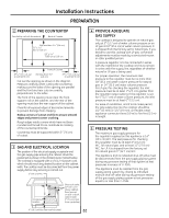
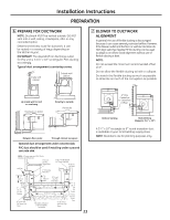
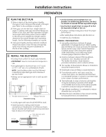
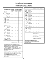
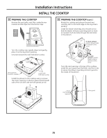
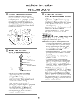
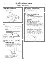
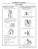
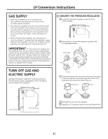
Installation Instructions INSTALL THE COOKTOP 10 PREPARE THE COOKTOP (cont.) Remove the blank 9-pin connector plug from the 9-pin receptacle on the bottom of the cooktop and discard. Connect the 9-pin plug on the blower assembly to the matching 9-pin receptacle on the bottom of the cooktop. Secure the connector cover to the cooktop using 3 screws, making sure the power cord comes out the U-shaped opening with the wires to the motor. 9-pin connectors Connector cover 11 INSTALL THE PRESSURE REGULATOR AND CONNECT Regulator Solid piping or flexible connector Union Solid piping or flexible connector Shut-off valve Pipe stub • For all connections, use a pipe sealant approved by local codes and resistant to the activity of L.P. gas. • Install the pressure regulator in the gas line as close to the cooktop inlet as possible to allow clearance for ventilation ducting. • Make sure the arrow on the body of the regulator is pointing straight up and toward the cooktop. Any other position will affect the output pressure of the regulator. This arrow indicates correct gas flow direction. • Install a manual gas line shut-off valve in an easily accessible location. 11 INSTALL THE PRESSURE REGULATOR AND CONNECT (cont.) NOTE: Instead of using solid piping to connect to the pressure regulator, an approved flexible metal appliance connector may be used between the shut-off valve and the pressure regulator, if local codes permit. Appropriate flare nuts and adapters are required at each end of the flexible connector. Make sure all the knobs are in the off position. Hook up the gas line and check for leaks. TEST FOR LEAKS WARNING: DO NOT USE A FLAME TO CHECK FOR GAS LEAKS! Do not use the cooktop until all connections have been leak tested. Perform leak test per the following instructions: 1. Purchase a liquid leak detector or prepare a soap solution of one part water, one part liquid detergent. 2. When all connections have been made, make sure all cooktop controls are turned to OFF and turn the gas supply valve to ON. 3. Apply the liquid leak detector or the soap solution around all connections from the shut-off valve to the cooktop. 4. A leak is identified by a flow of bubbles from the area of the leak. 5. If a leak is detected, turn the gas supply off. Tighten the fitting. Turn the gas on and test again. 1. If the leak persists, turn the gas supply off and contact your dealer for assistance. Do not attempt to operate the cooktop if a leak is present. IMPORTANT: Disconnect the cooktop and the individual shut-off valve from the gas supply piping system during any pressure testing of that system at test pressures greater than 1/2 psig. Isolate the cooktop from the gas supply piping system by closing the individual manual shut-off valve to the cooktop during any pressure testing of the gas supply piping system at test pressures equal to or less than 1/2 psig. 27
-
 1
1 -
2
-
3
-
4
-
5
-
6
-
7
-
8
-
9
-
10
-
11
-
12
-
13
-
14
-
15
-
16
-
17
-
18
-
19
-
20
-
21
-
 22
22 -
 23
23 -
 24
24 -
 25
25 -
 26
26 -
 27
27 -
 28
28 -
 29
29 -
 30
30 -
 31
31 -
 32
32 -
33
-
34
-
35
-
36
-
37
-
38
-
39
-
40
-
41
-
42
-
43
-
44
-
45
-
46
-
47
-
48
-
49
-
50
-
51
-
52
-
53
-
54
-
55
-
56
-
57
-
58
-
59
-
60
-
61
-
62
-
63
-
64
-
65
-
66
-
67
-
68
-
69
-
70
-
71
-
72
-
73
-
74
-
75
-
76
-
77
-
78
-
79
-
80
 |
 |
